 Profile
 Settings
 Refer your friends
 Sign out


Vernier Callipers
The vernier calliper was invented in 1631 by Pierre Vernier of France as a tool for obtaining extremely precise linear measurements. It has two graduated scales: a primary scale that looks like a ruler and a specifically graduated auxiliary scale called the vernier that slides parallel to the main scale and allows readings to be taken to a fraction of a division on the main scale.
A vernier calliper is a type of measuring device that is used to measure linear dimensions. With the help of the measuring jaws, it may also be used to measure the diameters of circular objects.
Vernier scales with 10 divisions of the same length as the main scale are also available. A vernier scale can improve the accuracy of both angular and linear measurements.
Different parts of Vernier Callipers
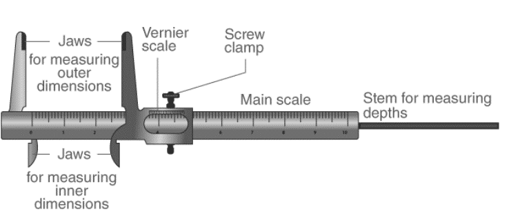
- Main Scale
It’s a big scale that runs the length of the vernier calliper’s body. Depending on the use, the reading on the primary scale could be in centimetres or millimetres. According to the SI units, 1 mm is the smallest primary scale division. The main scale is not moving.
- Vernier Scale
This is the smaller scale that moves along the main scale since it is attached to it. The opening of the jaws controls the movement of the vernier scale. The main purpose of the vernier scale is to ensure that the main scale reading is accurate by breaking it into smaller increments. A metric calliper’s vernier scale can be divided into up to 50 increments, with each division measuring 0.02 mm.
- Lower Jaws
One of the most distinguishing elements of a vernier calliper is its jaws. One of the jaws is coupled to the main scale and is fixed. The other jaw, which is coupled to the vernier scale, is adjustable. These jaws are primarily meant to grab items tightly. The lower jaw’s primary role is to measure outside dimensions such as diameter, width, and length.
- Upper Jaws
The upper jaws are similar to the lower jaws, except they are smaller. The upper section of the vernier scale is where these jaws are fastened. One jaw is stationary, while the other is moveable. The upper jaw’s primary purpose is to measure the inside dimensions of objects. Before taking the reading, the jaws are opened until they touch the edges of the objects. Upper jaws can be used to measure the inner diameters of things like hollow pipes and jars.
- Depth Rod
The depth rod can be used to measure the jars’ depths. It’s a long, thin rod near the bottom of the main scale. It’s easy to measure depth with a depth rod. The main scale’s edge is positioned on the object’s top surface, and the jaws are slowly opened. The extension of the depth rod is caused by the jaws opening. The jaws must be opened until the depth rod reaches the bottom of the object.
- Thumb Screw
At the bottom of the vernier scale, there is a screw. The thumbscrew’s main purpose is to give users a firm grip so that they may easily slide their jaws back and forth.
- Lock Screw
The lock screw’s principal purpose is to keep the jaws in place once the object has been firmly fastened between them. This also makes taking accurate readings a breeze.
Formulas of Vernier Calliper
The vernier constant is the other name for least count of vernier callipers. The difference between one main scale division and one vernier scale division is called the least count.
Mathematically, Least Count can be given as:
LC=1 MSD – 1 VSD
When the vernier scale has n divisions and it coincides with the the main scale at (n-1) division, the vernier calliper with the least count is:
LC=(1-n-1/n) ×MSD
The least count of vernier calliper is 0.1 mm.
In the above equations,
LC= least count
MSD= main scale reading
VSD= vernier scale reading
Uses of Vernier Calliper
- This is one of the most common applications for this device. It is used to investigate the expansion of materials as a function of temperature in order to determine their qualities. It is used to accurately measure various pieces of equipment in order to ensure correct fit. They can also be used to measure regular and irregularly shaped things from the inside or outside.
- Since the size of instruments have been measured in order to be suitable for surgery, the medical and surgical industries rely heavily on this gadget.
- The use of a vernier calliper is strongly advised while manufacturing or verifying the dimensions of a by-product to guarantee that the appropriate requirements are reached.
- These instruments are used in schools and engineering institutions to help students gauge several other instruments and items used in physics and many other subjects, as well as to correct zero mistakes. One of the few experiments in modern physics is using this equipment to measure the outer and inside dimensions of cylinder-shaped objects.
Screw Gauge
The screw gauge is a tool for precisely measuring the diameter of a thin wire or the width of a metal sheet. It consists of a U-shaped mount that is attached to a thimble with a screwed pin. A scale passed in mm is written side by side with the thimble’s axis. A screw gauge has a U-shaped metallic mount that allows it to measure even the smallest lengths with pinpoint accuracy.
A screw gauge, like Vernier callipers, has two scales: a key scale and an extra scale. The primary scale is a millimetre scale that has been reduced to 0.5 mm, while the secondary scale is divided into 50 uniform parts. The additional scale is located on the little metal cover that protects the user’s finger when sewing the screw gauge and measures one hundredth of the measurement.
By rotating the thimble, the gauge’s mandible is shifted. The Vernier revolving scale refers to the additional scale on the thimble. Furthermore, the thimble is designed in such a way that two thimble changes will allow the mandible to shift by 1 mm. This means that a single rotation will only move the mandibles 0.50 mm. The key scale is located on the “sleeve” portion of the screw gauge.
Components of Screw Gauge
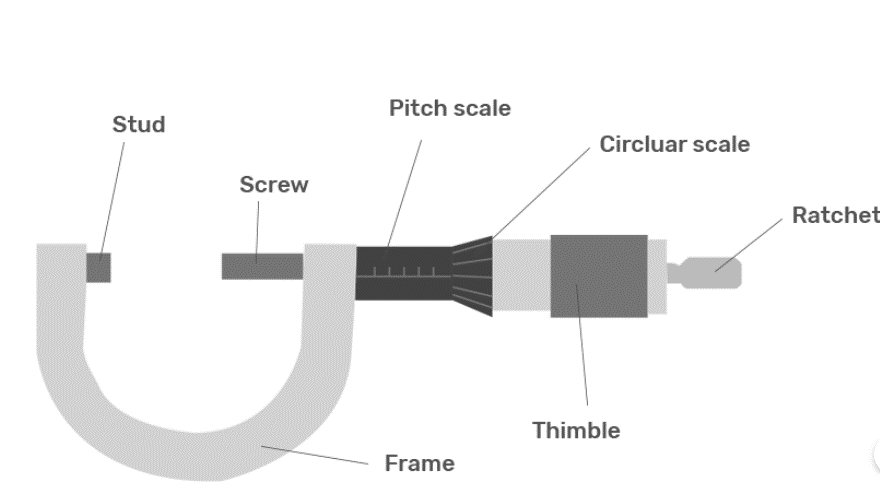
There are many different components of Screw Gauge:
- Frame: The screw gauge’s frame connects the anvil and the barrel, as well as holding the entire device together. To avoid measuring mistakes caused by flexion, expansion, and contraction, it is normally constructed quite thick. As the frame is substantial, it is weighty and has a large thermal mass, which prevents the screw gauge from heating up while a user holds it in their hands. Screw gauges should be used at room temperature (20 °C / 68 °F) because temperature might affect measurement accuracy.
- Anvil: The stud in the given diagram is also known as anvil. The spindle is moved towards the object to be measured, which is put on the anvil.
- Barrel: It’s also known as a sleeve or stock, and it’s a stationary component with linear or vernier markings on it. The barrel of some screw gauge versions is a rotatable cylinder, allowing for zeroing by changing the cylindrical barrel.
- Thimble lock: This element can be tightened to keep the spindle in position while measuring. It’s sometimes referred to as a lock nut or a lock ring.
- Spindle: The spindle will travel towards the anvil as the thimble is rotated.
- Thimble: This is the rotating portion of the screw gauge.
- Screw: This is the screw gauge’s key component that aids in measurement.
- Ratchet: It’s used to keep the thimble from rotating any further than it needs to.
Formulas of Screw Gauge
The following terms are used when we discuss about screw gauge:
- Pitch: The distance moved by the spindle per revolution, measured by sliding the head scale over the pitch scale in order to complete one full rotation is known as pitch of the screw gauge.
The pitch of the screw gauge can be calculated using the formula given below:

- Least count: The distance moved by the tip of the screw when driven through one division of the head scale is the screw’s least count.
The Least Count of the screw gauge can be calculated using the formula given by:
![]()
- Micrometer screw gauge: It is an instrument for measuring the diameter of thin wires and the thickness of tiny sheets like glass or plastics.
The least count of the micrometer screw gauge can be given by:
![]()
Uses of Screw Gauge
- A gauge number is used to describe the thickness of a metal sheet. We can determine the gauge number of a metal sheet by measuring its thickness in millimetres using a screw gauge. For instance, if a sheet’s thickness is 5.16 mm., the gauge number will be 6. The gauge number for a sheet with a thickness of 0.953 mm is 10. A conversion table can be used to determine the gauge number for various thicknesses.
- A wire’s diameter is measured in American wire gauge size. The gauge size can be determined by measuring the diameter of a wire after removing the insulation in mm with a screw gauge. For example, if a wire’s metric size is 52 mm, its A.W.G. size is ‘0.’ If a wire’s metric size is 5 mm, its A.W.G. size will be 10. A conversion table can be used to determine the A.W.G. size for various metric wire sizes.
- A screw gauge is used to determine the diameter of a steel rod used in building construction.
- It’s utilised in the industry to make machine components that meet certain specifications.
Conclusion
A screw gauge is a mechanical tool that allows you to precisely measure the diameter, radius, or thickness of a thin wire or thin metal sheet. A U-shaped frame and a spindle (or screw) attached to the thimble are the essential components of this instrument. The Pitch Scale, which is the major scale and is etched on the barrel with vertical lines, is one of two scales.
A vernier calliper is a type of measuring device that is used to measure linear dimensions. With the help of the measuring jaws, it may also be used to measure the diameters of circular objects. Vernier scales with 10 divisions of the same length as the main scale are also available; the reading procedure is similar to that described above. A vernier scale can improve the accuracy of both angular and linear measurements.


