Transistor amplifiers boost AC input signals that alternate between positive and negative values. The transistor must then be able to function between these two maximum or peak values, so some method of presenting the amplifier’s circuit layout is required. Biasing is a technique for accomplishing this.
Biasing is essential in amplifier design because it establishes the correct operating point of the transistor amplifier when it is ready to accept signals, reducing output signal distortion.
Also, drawing a static or DC load line over an amplifier’s output characteristics curves allows us to observe all of the transistor’s possible operating points, from fully “ON” to totally “OFF,” as well as the amplifier’s idle operating point or Q-point.
Any small signal amplifier’s goal is to amplify all of the input signal with the least amount of distortion possible in the output signal; in other words, the output signal must be an exact duplicate of the input signal, only bigger (amplified).
The voltage divider biassing used in the single stage common emitter amplifier circuit depicted above is known as “Voltage Divider Biasing.” Two resistors are used as a potential divider network across the supply, with their centre point giving the requisite base bias voltage to the transistor in this form of biassing configuration. In the construction of bipolar transistor amplifier circuits, voltage divider biassing is often used.
By keeping the Base bias at a constant stable voltage level, this approach of biassing the transistor considerably decreases the impacts of fluctuating Beta, , allowing for the best stability.
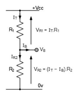
The potential divider network built by the two resistors R1, R2 and the power supply voltage determines the quiescent Base voltage (), as seen with current flowing through both resistors.
The overall resistance RT will then equal , resulting in a current of . The voltage generated at the junction of resistors and maintains the Base voltage () at a value lower than the supply voltage.
The supply voltage is divided in proportion to the resistance by the potential divider network in the common emitter amplifier circuit. Using the basic voltage divider formula below, you can simply compute the bias reference voltage.
When the transistor is fully “ON” (saturation), , the same supply voltage, , also controls the maximum Collector current, . The Collector current, , and the DC current gain Beta, of the transistor are used to calculate the Base current .
The forward current gain of a transistor in the common emitter configuration is defined by its Beta value, which is sometimes referred to as hFE on datasheets. The electrical parameter beta is integrated into the transistor during the manufacturing process. Because Beta ( hFE) is a fixed ratio of the two currents, IC and IB , it has no units. This means that a little change in the Base current will result in a big change in the Collector current.
Common Emitter transistors, like other transistors, have a variety of characteristics such as gain, resistance and impedance.
Common Emitter voltage gain: The ratio of the change in the input voltage to the change in the amplifier output voltage is known as common emitter voltage gain. Consider Vout and Vin as VL and VB , respectively.
When a transistor is used to amplify a signal, it is called a Common Emitter Amplifier. The following are the most prevalent uses:
An oscillator is an electrical circuit that generates a periodic, oscillating signal, most commonly a square or sine wave. It essentially converts direct current from a power source to alternating current. When we utilise a transistor in a circuit, it produces undamped oscillations at the circuit’s output terminals. With the help of a circuit schematic, we can show you how to use a transistor as an oscillator.
Below is a diagram of a transistor oscillator circuit. There are three sections to this circuit:
As we all know, when the flux in one coil rises, the flux in the other coil decreases, resulting in phase variation when the coil is fed to the other side. When we look at the output voltage of a common emitter amplifier, we see that it is always in the opposite phase of the input, indicating that one phase variation occurs from the input to the other side and the other occurs from the output to the input side via feedback circuit. As a result, in this case, the feedback oscillations will be perfectly in step with the nature of oscillations.
The transistor is utilised as a common emitter circuit in oscillator circuit design, with the emitter connected to both the base and collector terminals. A tank circuit has been connected between the input terminals, i.e. between the emitter and the base. The tank circuit is an electric circuit that produces oscillations by connecting an inductor (L) and a capacitor (C) in parallel. The base current fluctuates due to voltage and charge oscillations in the tank circuit, and the forward biassing of the base current varies as a result of this variation. As a result, the collector current begins to fluctuate on a regular basis.
To put it another way, the LC oscillations are sinusoidal in nature, and as a result, both the collector current and the base current vary sinusoidally. If the collector current varies sinusoidally, as shown in the picture, the output voltage obtained can be expressed as ICRL and regarded a sinusoidal output. When we plot the output voltage Vout against time, the curve we get is sinusoidal in form. Now, we need some energy in the tank circuit for continuous oscillations, but there is no battery or dc source available in this circuit.
We do this by using a soft iron rod to connect the mutual inductor L2 and L1 in the collector and base circuits. This soft iron rod will connect inductor L2 to inductor L1 , and a portion of the energy in the collector circuit will be transferred to the base side of the circuit due to mutual induction. As a result, the oscillation in the tank circuit is sustained and magnified on a constant basis.
The most in-demand component in the electronics sector is oscillators. In general, we separated it into two groups:
Electronic Transistors are small electronic devices that regulate current flow in a circuit. Because it can be changed to operate as a switch, Oscillator, and other electronic components, the transistor is a very significant electronic component used in circuits. A transistor can also be used as an amplifier. It’s employed when a circuit’s input signal isn’t strong enough.
In the Collector circuit of the Common Emitter Amplifier, there is a resistor. The voltage output of the amplifier is generated by the current passing through this resistor. The value of this resistor is adjusted so that the output voltage is half way along the transistor’s load line at the amplifier’s quiescent operating point, Q-point.
 Profile
 Settings
 Refer your friends
 Sign out