The propagation constant of a light wave can be changed by changing its frequency near the bandgap of a Bragg structure.. A stack of layers with alternate refractive indexes can form a Bragg structure.
The propagation constant is the measurement of changes in the amplitude and phase of a sinusoidal electromagnetic wave as it propagates across a medium. A transmission line or open space can be used. The Propagation Constant is a quantity with no dimensions. The value of the propagation constant is stated logarithmically.
Propagation constant
The amplitude and phase of a sinusoidal electromagnetic wave vary as it propagates in a particular direction, and the propagation constant is a measure of that change. The voltage, current in a circuit, or a field vector such as electric field strength or flux density can all be measured. The propagation constant itself is dimensionless and measures the change per unit length. The propagation constant monitors the change in the source quantity as it propagates from one port to the next in two-port networks and their cascades.
The phrase “propagation constant” is a misnomer because it typically changes greatly with. Although it is perhaps the most generally used phrase, many authors have given this amount a variety of other names. Transmission parameter, transmission function, propagation parameter, propagation coefficient, and transmission constant are all examples of these terms. When the plural is used, it implies that are being discussed independently but collectively, as in transmission and propagation parameters.
The propagation constant of a mode in a waveguide (such as a fibre) determines how the amplitude and phase of light with a particular frequency vary along the propagation direction z.
The optical frequency (or wavelength) of the light determines the propagation constant. The group delay and chromatic dispersion of the waveguide are determined by the frequency dependence of its imaginary portion.
Propagation constant diagram

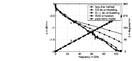
Propagation constant γ= α+jβ for an on-chip microstrip transmission line with passivation.
Constant Propagation is a hardware implementation optimization approach used by synthesis tools.
This is done by fine-tuning the algorithm that decides which parameters are set to keep it disabled. This method is not restricted to module boundaries, and the hardware can be optimised both inside and outside the module. The output port dependencies on the parameter configurations for the module are the basis for this two-way optimization.
Propagation Delay
The time it takes for the effect of a change in input to be evident at the output is known as the propagation delay of a logic gate. In other terms, propagation delay is the amount of time it takes for an input to reach the output. It is usually described as the difference between the times when the transitional input reaches 50% of its final value and the time when the output reaches 50% of its final value, demonstrating the effect of input change. The logic threshold of 50% is defined as the point at which the output (or, in this case, any signal) is assumed to flip states.

Example of propagation delay
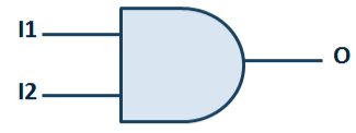
Consider the 2-input AND gate above figure, with input 1 2 transitioning from logic 0 to logic 1 and input l1 remaining stable at logic value 1. In effect, it will force the output 1 to transition as well. The effect will not appear instantly in the output, but after a set time interval. The transitions’ timing diagram is also presented. In this example, the propagation delay will be the time interval between I2 reaching 50% while rising and 1 reaching 50% while rising as a result of l2 transitioning.
On what factors propagation delay depends
Transition time of the input causing transition at the output:
The longer the transition time at the input, the longer the cell’s propagation delay. The signals should transition faster to reduce propagation delay.
The output load being felt by the logic gate
The larger the capacitive load at the cell’s output, the more work (and time) it will take to charge it. As a result, the propagation delay is longer.
Output transition time
The same two elements that control propagation delay also govern output transition time. In other words, a longer transition time and a higher load lengthen the signal’s transition time at the logic gate’s output. As a result, both of these should be reduced for better transition times.
Conclusion
The amplitude and phase of a sinusoidal electromagnetic wave vary as it propagates in a particular direction, and the propagation constant is a measure of that change The propagation constant of a mode in a waveguide (such as a fibre) determines how the amplitude and phase of light with a particular frequency vary along the propagation direction z. The time it takes for the effect of a change in input to be evident at the output is known as the propagation delay of a logic gate.
 Profile
 Settings
 Refer your friends
 Sign out


