A circuit diagram is a picture with symbols that have differed from one country to the next and have changed over time, but which are now, for the most part, internationally standardised. Simple components were frequently marked with symbols that were intended to represent some aspect of the device’s physical construction. In the case of a resistor, the symbol for that component dates back to the time when that component was made from a long piece of wire wrapped in such a way that it did not produce inductance, which would have made it a coil. As a result, these wirewound resistors are only used in high-power applications, with smaller resistors being cast from carbon composition (a mixture of carbon and filler) or manufactured as an insulating tube or chip coated with a metal film in place of them. Instead of the zig-zag symbol, the internationally standardised symbol for a resistor has been simplified to an oblong shape, sometimes with the value in ohms written inside it. It is also possible to represent the conductor with just a series of peaks on one side of the line instead of the more common “back and forth” symbol.
Alessandro Volta invented the first electric circuit in 1800, and it is still in use today. When Volta discovered that he could generate a steady flow of electricity by connecting bowls of salt solution together with metal strips, it was a game changer. The voltaic pile, which he later constructed out of copper, zinc, and cardboard discs that had been soaked in a salt solution, was the culmination of his efforts (an early battery). A wire running from top to bottom was successfully attached to the circuit, and the electric current flowed successfully through the circuit. The electrolysis process was the first practical application of electric current, and it was this process that resulted in the discovery of new chemical elements.
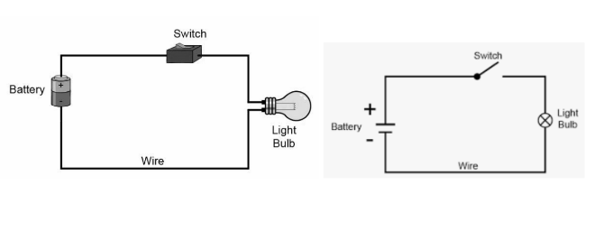
Electric circuits are a wonder to behold. Have you ever played the game Steady Hands? If not, you should. It is a circuit made up of two points connected by a twisty wire. The object of the game is to move a metallic object from one end of an electric wire to the other end of an electric wire. If you come into contact with the wire while moving this metallic object, the circuit will buzz and you will be thrown out. It’s a really fun game that can be made with items that you already have around the house. Let’s take a closer look at an electric circuit and its constituent parts in detail.
Electrical symbols are graphical representations of electrical and electronic components that are used in electronic and electrical systems. These symbols assist us in identifying a specific electronic device within a circuit…. National and international standards define the symbols used in the electrical industry. These symbols only represent the components of electrical and electronic circuits; they do not define the function or process that takes place in the circuits they represent.
A wire is a single, flexible strand or rod of metal that is usually cylindrical in shape and through which electric current flows. It is typically constructed of high-conductivity metals such as copper.
Connecting wires act as a conduit for electrical currents, allowing them to travel from one point on a circuit to another without being interrupted.
Wires crossing through other wires in a diagram, even though they are not connected to one another, is something we see quite frequently. As a result, it is preferable to have a hump, such as the one shown, to represent the crossing of a wire over another wire.
A resistor is a component of a circuit that prevents current from flowing through it.
When it comes to resistors, a variable resistor is one whose electrical resistance can be adjusted.
Rheostats are variable resistors that can be used to control the current flowing through a circuit by changing their resistance.
It is a three-terminal resistor with a sliding or rotating contact that is used to create an adjustable voltage divider by varying the resistance between the terminals.
In electrical engineering, a capacitor is a device that stores electrical energy in an electric field.
A voltage source is an electrical component that can maintain a constant voltage regardless of the resistance of the load or the current flowing through it.
A battery is a device that is made up of two or more electrochemical cells that are connected to the outside world.
It is a source hose with positive and negative terminals that change on a regular basis.
An electrical potential metre is a device that measures electrical potential.
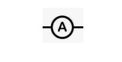
An instrument for measuring the flow of electricity.
Current can only flow in one direction through a semiconductor device with two terminals, which has two terminals.
It is known as an electric switch because it is a simple device that can be used to either break or complete an electric circuit.
Electric circuits and symbols are universally recognised symbols, which means that they are the same for everyone. An electronic symbol is a pictogram that can be used to represent a variety of electrical and electronic devices or functions, whereas an electric circuit is made up of a source of electrical energy, elements that transform, dissipate, or store this energy, and wires that connect the various components together.
Electrical symbols are graphical representations of electrical and electronic components that are used in electronic and electrical systems. These symbols assist us in identifying a specific electronic device within a circuit.
 Profile
 Settings
 Refer your friends
 Sign out