A potentiometer is a passive electronic component. By adjusting the placement of a sliding contact across a consistent resistance, potentiometers may regulate its position. In a potentiometer, the full input voltage is applied over the entire length of the resistor, while the output voltage is the difference between the fixed and sliding contacts.
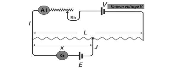
The potentiometer is made up of L, a long resistive wire, and V, a known EMF battery whose voltage is known as the driving cell voltage. Connect the battery terminals to the two ends of L to form a primary circuit. On one end, the primary circuit is connected to the cell whose EMF E is to be measured, and on the other end, it is connected to the galvanometer G. This is thought to be a secondary circuit.
Potentiometers are divided into two categories:
Linear potentiometers have special characteristics that ensure long trouble-free life in the roughest of conditions, from motorsport to structural monitoring, and from detecting linear position or displacement in a wide range of manufacturing and process equipment. They are exceptionally easy to operate in comparison to other devices, have infinite resolution, and output that is proportional to stroke length. They are also quite durable. The voltage across a circuit’s branch, the internal resistance of a battery cell, and the comparison of a battery cell to a standard cell are all common uses for this potentiometer.
To begin answering the issue of what is a linear potentiometer, consider the many components of this device. A linear taper potentiometer is made up of three pins that adjust to a voltage flow and generate a regulated voltage output that is related to its sliding components. It consists of a pin attached to an adjustable slider that moves with the resistor, changing the resistance between them. The remaining two pins are linked at both ends of the output circuit, where the slider slides on the resistor through a track that is tied to the resistor. Either DC or AC voltage is used to stimulate the resistance element.
The linear potentiometer’s measurement principle is based on a potential divider. Rod operated linear potentiometers are frequently coupled to an internal slider or wiper carrier that runs on a resistance track. The rod will be attached to a gadget or object that has to be measured. The linear potentiometer divides an applied regulated voltage proportionally over its working range and outputs a proportional voltage that is proportional to the wiper position. The resistance inside the circuit changes with the location of the wiper and is thus proportional to the voltage decrease. The distance can be calculated by the change in voltage because the resistance changes proportionally to the actual travelled path by the sliding contact.
We’ve only gone through the fundamentals of potentiometers so far. Potentiometers come in a variety of shapes and sizes, with rotary and linear potentiometers being the most prevalent. We won’t discuss linear ones in this post; instead, we’ll focus on rotary ones. The crucial thing to remember is that, while the basic constructional elements of both potentiometers differ, the functioning principle of both types of potentiometers is the same.
Potentiometers of the rotary kind are mostly used to provide adjustable supply voltage to a portion of electronic and electrical circuits. A common example of a rotary potentiometer is the volume controller of a radio transistor, where the rotating knob controls the supply to the amplifier.
A consistent resistance is put in a semi-circular pattern between two terminal contacts on this type of potentiometer. A central terminal on the gadget is connected to the resistance through a sliding contact attached to a rotary knob. Rotating the knob adjusts the semi-circular resistance’s sliding contact. To measure voltage, a resistance end contact and a sliding contact are employed. The potentiometer is referred to as the POT in short. In substation battery chargers, POT is also used to control the charging voltage of a battery. Other uses for rotary type potentiometers that require smooth voltage control are diverse.
An electronic circuit is a potentiometer. This is a fairly basic instrument that can be used to compare EMF between two cells as well as calibrate ammeters, voltmeters, and wattmeters. It has a wide range of applications and uses. The resistance of a potentiometer is fixed, and it blocks or resists the flow of electrical current around a circuit. A potentiometer with three terminals is commonly referred to as a “pot.” Today’s potentiometers are significantly smaller and more precise than the early massive and bulky variable resistances, and they exist in a number of shapes and sizes, as do other electrical components, with names like variable resistor, present, trimmer, and rheostat, as well as variable potentiometer.
 Profile
 Settings
 Refer your friends
 Sign out