 Profile
 Settings
 Refer your friends
 Sign out


Rectifiers are electric circuits that convert alternating current to direct current. There are two types of rectifiers: half wave rectifiers and full wave rectifiers (also known as full wave rectifiers). When using a half-wave rectifier, a significant amount of power is lost, making it unsuitable for applications that require a smooth and consistent supply. The full wave rectifiers are used to provide a more smooth and consistent supply. In this article, we’ll take a look at the operation and characteristics of a full wave rectifier and how it works.
Full Wave Rectifiers are defined as follows
A full wave rectifier is defined as a rectifier that converts an alternating current cycle into a pulsating direct current cycle in its entirety. Full wave rectifiers, in contrast to half wave rectifiers, which use only the first half of the input alternating current cycle, use the entire cycle. The half wave rectifier has a lower efficiency than the full wave rectifier, but the full wave rectifier can compensate for this.
Full Wave Rectifier Circuit
It is possible to construct the circuit of the full wave rectifier in two different ways. The first method makes use of a transformer with a centre tap and two diodes. A centre tapped full wave rectifier is the name given to this configuration. This method employs a standard transformer with four diodes arranged in a bridge configuration to achieve the desired result. A bridge rectifier is what we’re talking about here.
The circuit for the full wave rectifier is composed of a step-down transformer and two diodes that are connected and centre tapped together in series. The output voltage is obtained by measuring the voltage drop across the connected load resistor.
The Operation of a Full Wave Rectifier
The input alternating current (AC) supplied to the full wave rectifier is extremely high. The step-down transformer in the rectifier circuit is responsible for converting the high voltage alternating current into low voltage alternating current. The anode of the centre tapped diodes is connected to the secondary winding of the transformer and the cathode is connected to the load resistor. On alternating current’s positive half cycle, the top half of the secondary winding becomes positive and the second half of the secondary winding becomes negative.
The forward bias of diode D1 is created because it is connected to the top of the secondary winding, whereas the reverse bias of D2 is created because it is connected to the bottom of the secondary winding. During the positive half cycle, diode D1 is created because it is connected to the top of the secondary winding. As a result, diode D1 will conduct, resulting in a short circuit, while diode D2 will not conduct, resulting in an open circuit.
Because the top half of the secondary circuit becomes negative and the bottom half of the secondary circuit becomes positive during the negative half cycle, the diode D1 is reverse biassed and the diode D2 is forward biassed during the negative half cycle. Because of this, DC voltage is obtained for both the positive and negative half cycles in a full wave rectifier.
Formula for a Full Wave Rectifier
Peak Inverse Voltage
The peak inverse voltage of a diode is the highest voltage that it can withstand in the reverse-biassed direction before it fails completely. The peak inverse voltage of a full-wave rectifier is twice as high as the peak inverse voltage of a half-wave rectifier. The maximum potential difference between D1 and D2 is 2V.
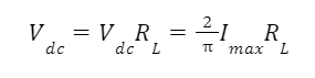
DC Output Voltage
The average value of the DC output voltage can be calculated using the following formula:
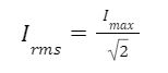
RMS Value of Current
This formula can be used to calculate the current’s RMS value, which is the root mean square value.
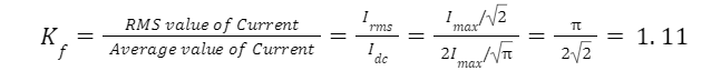
Form Factor
It is possible to calculate the form factor of a full wave rectifier using the following formula:
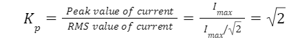
Peak Factor
The peak factor of a full wave rectifier can be calculated using the following formula:
Rectification Efficiency
The following formula can be used to calculate the rectification efficiency of a full-wave rectifier:
η=DC Output Power/AC Output Power
The efficiency of the full wave rectifiers is 81.2%.
The Benefits of Using a Full Wave Rectifier
Full wave rectifiers have a rectification efficiency that is twice as high as that of half wave rectifiers. Half wave rectifiers have a rectification efficiency of 40.6 percent, whereas full wave rectifiers have a rectification efficiency of 81.2 percent (see figure).
When working with full wave rectifiers, the ripple factor is low, so a simple filter is required.
The ripple factor of a full wave rectifier is 0.482, whereas the ripple factor of a half wave rectifier is approximately 1.21.
Full wave rectifiers produce higher output voltage and output power than half wave rectifiers, which means that they are more efficient than half wave rectifiers.
Compared to half wave rectifiers, full wave rectifiers have only one disadvantage: they require more circuit elements than half wave rectifiers, which makes them more expensive.
Conclusion
In electrical engineering, a full wave rectifier is defined as a type of rectifier that converts both halves of each cycle of an alternating wave (AC signal) into a pulsating direct current (DC signal). Full-wave rectifiers are used to convert alternating current to direct current, and their construction necessitates the use of multiple diodes. The process of converting an alternating current signal to a direct current signal is known as full wave rectification.
