Profile
 Settings
 Refer your friends
 Sign out


Impedance is an important concept in the study of electronics. Derived from the study of AC analysis, impedance, which is denoted by the letter ‘Z’, measures the resistance (R) to the flow of electricity in a circuit. This resistance, named after its founder, is measured in ohms. Impedance and resistance remain the same in DC systems. They are defined as the voltage that is present across any component divided by the current flowing through it (R = V/I). Due to components such as capacitance and inductance in AC circuits (which are frequency-dependent), the concept of ‘reactance’ enters the structure of impedance.
Formula of Impedance
- Impedance is a concept that is mostly a generalisation of resistance.
Resistance R = V/i (where R is a numerical value with unit ohms)
- We redefine Ohm’s law for changing electric currents as I = E/Z.
- In I = E/Z, ‘Z’ is the representation for impedance. It opposes all types of current, whether the current is changing or remains unchanged.
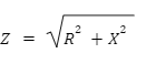
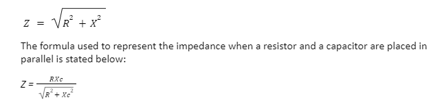
The formula used to represent the impedance when a resistor and a capacitor are placed in series is stated below:
The characteristics of impedance
- Frequency is a factor which affects the impedance of a capacitor.
- At lower frequencies (Zc -> ∞ and F -> zero), a capacitor is bound to behave like an open circuit.
- At higher frequencies (Zc -> zero and F -> ∞), a capacitor is bound to behave like a short circuit.
- At intermediate frequencies, a capacitor’s impedance is given as Zc.
Therefore, it can be said that because impedance is influenced by reactance (X) and resistance (R), it is also influenced by frequency (F), and the value of impedance varies with frequency.
Measuring the impedance value
Since the effects of capacitance and inductance vary with the frequency of the current that moves through the circuit, it is more complicated than resistance. Resistance has the same impact irrespective of frequency.
- Impedance cannot be measured as readily as resistance since it is an AC attribute.
- Connecting an Ohm-metre across an amplifier’s input or output only shows the DC resistance.
- Instruments that can be used are a signal generator, an oscilloscope, and a decade resistance box or a resistor that is variable to measure input and output impedance at a given frequency.
The Structure Of Impedance In Parallel
To find the structure of impedance of a single resistance and reactance linked in parallel, the impedance of each parallel branch must be calculated.
- However, because there are only two parallel components, R and X, we can apply the conventional equation for two parallel resistances.

- The vector sum of R and X are calculated so that the product of both gets divided by it. Since we are handling AC supplies and frequencies in this case, the resistive component here is out-of-phase (90o) with the reactive component.
- When ‘n’ number of branches consisting of complex impedances are connected in parallel, the total impedance will be equal to the vector sum of all the parallel branches.
The input impedance
- Also represented as ZIn, the input impedance is seen by anything that is connected to a circuit or device’s input (for example, an amplifier).
- It is the sum of all the resistance, capacitance, and inductance present inside the circuit or device which is linked to the input.
- In most cases, input impedances should be high, that is, at least ten times that of the circuit (or component) sending the signal to the input.
- This guarantees that the input does not ‘overload’ the signal source, resulting in a significant reduction in signal intensity (voltage).
The value of ZIn can range from tens of ohms (Ω) to a few thousand ohms (kilo-Ω k) to millions of ohms (Mega-Ω M) for bipolar and FET transistor circuits.
The output impedance
- Also represented as ZOUT, the output impedance is equivalent to a voltage source in series with an output impedance.
- Output impedances should typically be lower, less than a tenth of the load connected to the output.
- Since much of the signal’s voltage is lost inside the circuit, pushing current through the output impedance ZOUT, an output impedance that is too high will be unable to send a sufficiently strong signal to the load.
The impedance with low output
- This case scenario is applicable when ZOUT << ZLOAD.
- Less voltage is lost in this scenario since the source voltage appears across the load.
- This is considered the best arrangement.
The impedance with high output
- This case scenario is applicable when ZOUT >> ZLOAD.
- Most voltage is lost in this scenario since the output current is driven out through the output impedance.
- This is considered an unsatisfactory arrangement.
The impedances that are matched
- The output current is driven by the other half of VSOURCE, which appears across the load and is lost when it sends the output current through the output impedance.
- Since it supplies the highest power to the load, this arrangement is advantageous in particular cases (such as an amplifier that drives a loudspeaker).
- It’s worth noting that feeding the output current through ZOUT wastes an equal amount of power, resulting in 50 per cent efficiency.
Conclusion
The relationship between voltage and current for an input that is sinusoidal is impedance. When connecting a loudspeaker to an audio system, the term impedance is usually expressed as a numeral of Ω written next to many sockets – input or output. In various technical areas, the term impedance refers to a resistance to work being done. One may review the vector addition method used for the calculation of impedance for a detailed study on the subject. Finally, the structure of impedance and related mathematical equations may be studied in-depth.