 Profile
 Settings
 Refer your friends
 Sign out


The rectifier circuit converts AC (Alternating Current) to DC (Direct Current). Half-wave, full-wave, and bridge rectifiers are the three most common types of rectifiers. All of these rectifiers have the same fundamental purpose of current conversion, however they do not transfer current from AC to DC efficiently. The full wave rectifier with centre tap as well as the bridge rectifier convert efficiently. In electronic power supplies, a bridge rectifier circuit is a common component.
Bridge Rectifier
The bridge rectifier’s primary function is to convert AC power to DC electricity. To improve the bridge rectifier, a filter is also employed inside the circuit. To power the electronic components from the available AC mains supply, many electronic circuits require a rectified DC supply.
Rectifiers are mostly used to convert AC power into DC power.
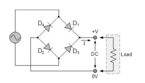
Bridge rectifiers are a form of Full Wave Rectifier that efficiently converts alternating (AC) current to direct (DC) current by using four or more diodes in a bridge circuit design.
Construction
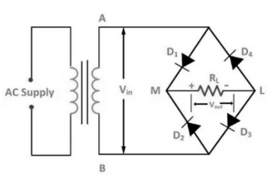
A resistor RL and four diodes D1, D2, D3, and D4 make up a bridge rectifier or bridge full wave rectifier circuit. These four diodes are coupled in a closed-loop design to convert alternating current to direct current efficiently.
The main benefit of a bridge rectifier configuration is that it saves money and space by eliminating the need for an expensive centre-tapped transformer.
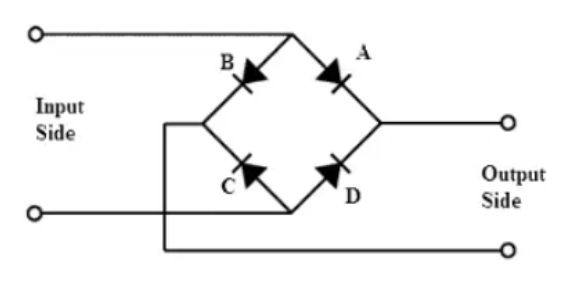
The input signal is applied to terminals A and B, and the output DC signal is obtained through Resistor RL, which is linked between terminals C and D.
Working of Bridge Rectifier
When a positive or negative signal is applied across a bridge rectifier, the signal alternates between positive and negative cycles.
Terminal B becomes negative and terminal A becomes positive during the positive half cycle. D1 and D3 become forward biased, whereas D2 and D4 become forward biased as a result.
During both the negative and positive half cycles, the current flow across resistor RL is the same. The output DC signal’s polarity can be totally positive or completely negative. We can get a completely negative voltage by reversing the direction of diodes.
Properties of Bridge Rectifier
Ripple Factor
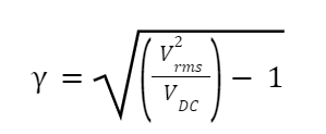
The smoothness of the output DC signal is what the ripple factor is. Smooth DC signals have fewer ripples, while pulsing DC signals have more. A ratio of ripple voltage to pure DC voltage can be defined as ripple factor.
The Formula for Ripple Factor is given by:
Where,
Vrms= Root Mean Square Voltage
VDC = Average Voltage of DC Supply
Generally the ripple factor for a Bridge Rectifier is considered to be 0.48.
Bridge Rectifier Efficiency
The efficiency of a bridge rectifier can simply be defined as the efficiency with which it converts AC to DC. The ratio of DC output power to AC input power can be used to calculate the Bridge Rectifier’s efficiency.
In an ideal world, the Bridge Rectifier’s efficiency would be 81.2 percent.
The efficiency of a bridge rectifier can be calculated using the following formula:
η=DC Output PowerAC Output Power
Advantages and Disadvantages of Bridge Rectifier
Because of their low cost, great reliability, and compact silicon diodes, bridge rectifiers have become widely available. Here’s a summary of the benefits and drawbacks of bridge rectifiers.
Advantages
- The efficiency of a bridge rectifier is higher than that of a half-wave rectifier. The efficiency of a bridge rectifier is comparable to that of a centre-tapped full-wave rectifier.
- In comparison to a half-wave rectifier’s output DC signal, the bridge rectifier’s output signal is smoother.
- The flow of current is allowed throughout both negative and positive cycles, unlike a half-wave rectifier. As a result, the output DC signal is nearly identical to the input AC signal.
Disadvantages
- It has a complicated circuit made up of four distinct diodes.
- The power loss of a bridge rectifier is high.
Types of Bridge Rectifiers
The following parameters are used to classify bridge rectifiers: kind of supply, controlling capability, bridge circuit designs, and so on. Bridge rectifiers are divided into two types: single-phase and three-phase rectifiers.
Uncontrolled, half-controlled, and fully controlled rectifiers are the three types of rectifiers. The next sections go through some of these many types of rectifiers.
Single Phase and Three Phase Rectifiers
These rectifiers are determined by the type of supply, such as single-phase or three-phase. For converting AC to DC, a single phase bridge rectifier requires four diodes, but a three-phase rectifier uses six diodes. Depending on the circuit components such as diodes, thyristors, and so on, these might be uncontrolled or controlled rectifiers.
Uncontrolled Bridge Rectifiers
As illustrated in the diagram, this bridge rectifier uses diodes to rectify the input. Since the diode is a unidirectional device, current can only flow in one way.
This diode design in the rectifier prevents the power from varying based on the load required. As a result, this type of rectifier is used in power supplies that are either constant or fixed.
Controlled Bridge Rectifier
Instead of uncontrolled diodes, controlled solid-state devices such as SCRs, MOSFETs, IGBTs, and other devices are used in this form of AC/DC converter or rectifier to alter the output power at different voltages. The output power at the load is varied appropriately by triggering these devices at various times.
