Reactance (X) is defined as the obstruction present in alternating current by either inductance or capacitance in electrical circuits. The term ‘reactance’ was coined by M. Hospitalier, a French engineer, in the year 1893. It is important to understand that reactance and resistance are not the same. The difference between reactance and resistance is that energy is stored in reactance momentarily, but resistance loses energy continuously. Resistance and reactance are both measured in Ohms. If the values are positive, it indicates inductance. If values are negative, it indicates capacitance. Perfect inductors and capacitors should have null resistance. The letter X represents the reactance. Reactance is used in electrical circuits to compute phase and amplitude changes.
Reactance is additionally present with resistance in conductors carrying alternating current.
Reactance – Types
1. Inductive Reactance
This type of reactance is associated with a magnetic field that surrounds a current-carrying coil of wire. When an alternating current is passed through a conductor or inductor, it sets up an alternating magnetic field. The changing magnetic field is the consequence of the current that oscillates back and forth.
The function of an inductor is to contradict the alteration in current and make this alteration in current lag behind those in voltage. A perfect inductor in an alternating current circuit has an inhibitive effect on the change in current. This shows a phase shift or delays in alternating current with alternating voltage. A perfect inductor with null resistance will show current to lag behind the voltage by 90 degrees.
Inductive reactance can restrict the power capacity of the AC transmission line in electrical power systems. This happens because the entire power is not transferred completely when the voltage and current are not in phase. Real work is not done when the transfer of power is negative.
Inductive reactance (XL) is known to be directly proportional to frequency(f) and the inductance(L).
The formula for inductive reactance is,
XL = ⍵L = 2𝜋fL
The inductive reactance effect is measured in Ohms.
The formula for average current through inductance(L) that is in series with an AC voltage with RMS amplitude(A) and frequency(f) is
2. Capacitive Reactance
This type of reactance is associated with an electric field that surrounds a current-carrying coil of wire. A capacitor is a device that embodies two conductors that are separated by a dielectric(an insulator). A capacitor obstructs changes in the potential difference or voltage across the plates. It retards current flow by alternating the voltage to lag behind the alternating current. This relation is just opposite to that of inductors.
When a direct current is applied to a capacitor, it shows a positive accumulation and a negative accumulation on the other side. The source of the opposition is given by the electric field that has been accumulated by these charges. If the potential in the circuit is completely balanced by the applied voltage, the current value becomes zero.
Suppose the capacitor is given an alternating current supply. In that case, it will only aggregate some amount of charge before the polarity of the potential difference changes. Finally, the charge will be returned to the source.Fewer charges will be accumulated when the frequency is high, and there will also be low opposition to the current.
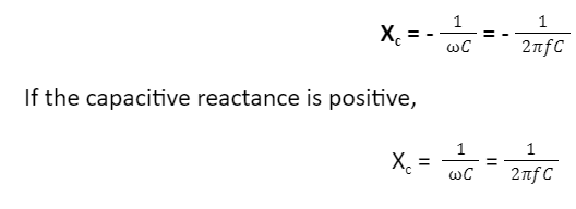
The capacitive reactance (Xc) is known to be inversely proportional to the frequency (f) or the angular frequency (⍵).
The formula for capacitive reactance is

If the frequency(f) is zero, then the capacitive reactance will be infinite. It behaves like an open circuit.
If frequency becomes infinite, the capacitive reactance will be zero. It behaves like a short circuit.
How Does Reactance Work?
When an alternating current flows through a reactance component, alternative energy is stored in it and released in the form of an electric or magnetic field. It is an inductive reactance in the case of a magnetic field. The reactance is capacitance reactance when it is an electric field. Imaginary positive values are given to inductive reactance. Imaginary negative values are given to capacitive reactance.
Examples Of Reactance
This section will include some examples of reactance.
An example is the reactance effect as a result of electronic components. The inductors and capacitors will oppose electric currents because of their inductive and capacitive resistances.
The other example of reactance is inductance and capacitance that is observed in transmission lines and magnetic coils, respectively.
Applications
In AC circuits, inductive reactance is used to protect against a surge in voltage.
Both inductive reactance and capacitive reactance are used in telecommunication devices.
A circuit containing both the inductive reactance and capacitive reactance is used to analyse amplitude, power factor, and phase changes that occur in the circuit.
Conclusion
The reactance definition is the obstruction that is present in alternating current either by inductance or capacitance in electrical circuits. If the values are positive, it indicates inductance. If values are negative, it indicates capacitance. The phrase ‘reactance’ was coined by M. Hospitalier, a French engineer, in the year 1893. There are predominantly two types of reactance – Inductive reactance and capacitive reactance. When an alternating current flows through a reactance component, alternative energy is stored in it and released in the form of an electric or magnetic field. It is an inductive reactance in the case of a magnetic field. The reactance is capacitive reactance when it is an electric field. Some examples of reactance are a reactance effect as a result of electronic components, and inductive reactance and capacitive reactance are used in telecommunication devices.
 Profile
 Settings
 Refer your friends
 Sign out


