Many network theorems are used in electronics and electrical engineering to solve complicated and multi-loop circuits.
According to the reciprocity theorem, the flow of current in any circuit or network is caused by a single voltage source within any specific branch of the circuit. Once the source is transferred to that specific branch of the circuit, this is comparable to the current value within the original branch wherever the voltage source was positioned.
Reciprocity Theorem Statement
According to the Reciprocity theorem statement the value of current obtained in any branch of an electrical circuit or network due to a single voltage source (V) in the circuit or network is the same as the value of current flowing through that branch when the source was originally connected and when the source was again connected to the branch where the value of current was originally determined.
The reciprocity theorem statement is used in both linear and bilateral networks where the circuit has just one independent source. It is utilized in both DC and AC circuits. In layman’s terms, the reciprocity theorem asserts that when the locations of any network’s voltage and current sources are switched, the same or equal amount of voltage and current flows through the circuit.
Steps to solve a Reciprocity Theorem
The steps to solve a Reciprocity Theorem are as follows:
- First, choose the branches in the circuit where reciprocity must be generated.
- Any normal network analysis approach may be used to determine the current flow within the branch.
- The voltage sources can be switched between the branches that have been chosen.
- Measuring current flow inside the branch, wherever the voltage source previously existed
- It is then noticed that the current obtained during the previous connection (i.e., the second step) and the flow of current measured after the source is exchanged (i.e., the fourth step) are equal.
When the ammeter and voltage source are utilized in the reciprocity theorem, it must be perfect. As a result, the voltage source’s internal resistance must be zero. If the reciprocal theorem is used, the circuit can be simple; otherwise, it can be complicated. Each complicated reciprocal network, on the other hand, may be reduced to a simple circuit. Based on the reciprocity theorem, the voltage supply and output current are equally movable in a linear passive network.
Explanation of Reciprocity Theorem:
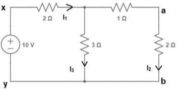
Reciprocity theorem can be explained with the help of the following circuit:

Assume we wish to test the validity of the reciprocity theorem in branches x-y and a-b.
To do so, we first calculate the current via the branch a-b as follows: Equivalent resistance between x-y = (3×3)/6 + 2 = 3.5Ω
As a result,
current I1 =10/3.5 A
=2.86 A.
The current via branches a-b may now be estimated using the current division formula as follows:
I2= (3x I1) / (3+3)
=2.86/2
=1.43A
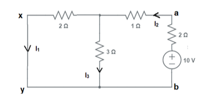
Change the location of the voltage source and place it in branch a-b, as illustrated below:

We want to determine the current value in branch x-y, which is the branch where the source was initially stored before being transferred to branch a-b, where we calculated the current.
The following calculations are used to determine the equivalent resistance between terminals a-b:
=2+1+6/5
=4.2Ω
Current I2 =10/4.2
=2.38A
Using the current division rule, the current in branch x-y may be calculated as follows:
I1 = (2.38 x 3)/5
=1.43A
As a result, I1 and I2 have the same value.
Maxwell’s reciprocal theorem
Maxwell’s reciprocal theorem, also known as the Maxwell’s Reciprocal rule, is a technical connection that equals two distinct distortions in an elastic structure under force. It may be used to either minimize the number of components estimated in a specific situation or to ensure that the computation properly projected the equivalence of two different distortions.
Maxwell’s reciprocal theorem is a fundamental technique in structural engineering.
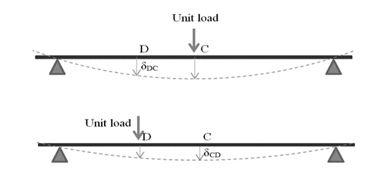
A simple example of Maxwell’s reciprocal theorem is illustrated in the diagram below.

A beam is supported at both ends.
A unit load is applied at point C in the center (or simplicity as an example).
The beam is deflected not just at the center but also along its whole length.
Let the deflection at point D be denoted by δDC.
According to Maxwell’s reciprocal theorem, the deflection at D caused by a unit force at C is the same as the deflection at C caused by a unit load at D.
δCD = δDC in our notation.
The lower diagram at the top, illustrates the second situation.
Conclusion
Therefore, the Reciprocity theorem statement may be phrased as when the locations of voltage and current sources in any network are switched, the quantity or magnitude of current and voltage flowing in the circuit stays constant.
The reciprocity theorem is utilized to solve several DC and AC networks that are used in electromagnetic electronics. There are no time-varying elements in these circuits.
 Profile
 Settings
 Refer your friends
 Sign out


