Current electricity
The formula for current electricity are as stated below |
| Description |
Formula |
| Formula for current |
Here, Δq is the charge flown through the circuit and Δt is the time in which the charge has flown. |
| Electric current in a conductor(wire) |
I=nAeV_d
v_d=λ/τ
Here, n is the number of free electrons, A is the area of conductor, e is the charge of an electron,
V_d is the drift velocity, λ is the linear charge density and τ is the relaxation time. |
| Potential difference using ohm’s law |
V=IR
Here, V is the potential difference, I is the current flowing through the conductor and R is the resistance offered by the conductor. |
| Resistance in terms of resistivity |
R=ρl/A
Here, ρ is the resistivity of the material of the conductor, l is the length of the conductor and A is the area of cross section of the conductor. |
| Change in resistance due to temperature |
R=R_0 (1+αΔT)
Here, R is the resistance, R_0 is the initial temperature, is the temperature coefficient of the resistivity and ΔT is the change in temperature. |
| Electric power |
P=VI
Here, P is the power, V is the potential difference and I is the current.
Also,
P=I^2 R
P=V^2/R |
| Heat energy released due to current |
H=VIt
also
H=I^2 Rt
H=V^2/R t
Here, H is the heat released in joules, V is the potential difference, R is the resistance, I is the current and t is the total time the current was flowing through the conductor. |
| Equivalent resistance when resistors are connected in series |
Req=R_eq=R_1+R_2+R_3+⋯+R_n
Here, R_eq is the equivalent resistance, R_1,R_2,R_3 are the resistance of the resistors. |
| Equivalent resistance when resistors are connected in parallel |
1/R_eq =1/R_1 +1/R_2 +1/R_3 +⋯+1/R_n |
| Potential difference when cells are connected in parallel |
E_eq=((ε_1/r_1 +ε_2/r_2 +ε_3/r_3 +⋯+ε_n/r_n ))/(1/r_1 +1/r_2 +1/r_3 +⋯+1/r_n )
Here, ε_1,ε_2,ε_3
are the emf of the cells and r_1,r_2,r_3are the internal resistance of the cells. |
| Ammeter using galvanometer |
To measure the maximum current I using a galvanometer, we need to connect a shunt resistance in parallel with the galvanometer.
The value of the resistance is calculated as:
S=(I_g R_g)/I
Here, S is the value of shunt resistance,
Ig is the current through galvanometer, Rg is the resistance of the galvanometer and I is the maximum current to be measured. |
| Voltmeter using galvanometer |
To measure a potential difference using a galvanometer, we need to connect a series resistance with it.
The value of the resistance that needs to be connected is:
Rs=VIg-Rg
Here, V is the maximum potential difference to be measured, I_g
is the current through galvanometer andR_g is the resistance of the galvanometer. |
Electric current formula
The formula for electric current are as stated below |
| Description |
Formula |
| Electric current |
I=q/t=ne/t
Where I= strength of current; q-charge; t- time |
| Resistance |
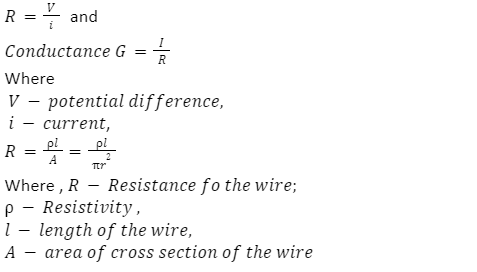
![]() |
| Variation of resistance with the temperature |
R_T=R_° [1+α(t)]
→α=(R_(t-) R_(° ))/(R_° (t) ) l°∁
α=((R_1-R_2 ))/(R_1 (t_2-t_1 ) ) l °∁
Here,
R = resistance at temperature t°∁
R° = resistance at temperature 0°∁= temperature coefficient of resistance |
| Conductivity |
Reciprocal of resistivity.
σ=1⁄ρ
Where – σ -conductivity, ρ -resistivity |
| Terminal voltage |
Case-1: When battery is delivering current
V=E-ir or i=E/R+r
Where
V -terminal P.d, E – emf of the cell, r -internal resistance of the cell, R- external resistance.
Case 2: when battery is charging
V=E+ir |
| Kirchhoff’s laws |
Kirchhoff’s First laws:
∑_ ^ i=0 at any junction.
Kirchhoff’s second law:
∑_ ^ iR=0 in a closed circuit. |
| Metre Bridge |
![]() Where x – unknown resistance of given wire, R-resistance in the resistance box, l1-balancing length from left end of the bridge to Jockey.
Where x – unknown resistance of given wire, R-resistance in the resistance box, l1-balancing length from left end of the bridge to Jockey.
- ρ=xA/l=x (πr^2)/l
Where ρ -Resistivity of the wire,
x -resistance of wire,
A – area of cross section of the wire,
l -length of the wire. |
| Potentio Meter |
Emf of cell in the secondary circuit
E_s=Iρl
- Comparison of emf’s of two cells: E1/E2=l1/l2
Where E1 and E2-emf of the first and second cell, l1 and l2- the balancing lengths of individual cells respectively.
- r= R(l1-l2)/l2
|
Electromagnetic Induction Formula
The formula for electromagnetic induction are as stated below |
| Description |
Formula |
| Magnetic Flux |
The magnetic flux through a plane of area dA placed in a uniform magnetic field B is given as
ϕ=∫ B ⃗∙dA ⃗
When the surface is closed, then magnetic flux will be zero. This is due to magnetic lines of force are closed lines and free magnetic poles is not exist |
| Electromagnetic Induction: Faraday’s Law |
First Law: Whenever magnetic flux linked with a circuit changes with time, an induced emf is generated in the circuit that lasts as long as the change in magnetic flux continues.
Second Law: According to this law, the induced emf is equal to the negative rate of change of flux through the circuit.
E = -dϕdt |
| Lenz’s Law |
The direction of induced emf or current in the circuit is in such a way that it opposes the cause due to which it is produced. Therefore,
E = -dϕ/dt |
| Induced emf |
Induced emf is given as
E = -N(dϕ/dt)
E = -N((ϕ_1- ϕ_2)/t) |
| Induced Current |
Induced Current is given as
I=E/R = N/R(dϕ/dt)= N/R((ϕ_1- ϕ_2)/t) |
| Self – Induction |
Change in the strength of flow of current is opposed by a characteristic of a coil is known as self-inductance.
It is given as ϕ=LI
Here, L = coefficient of self – inductance
Magnetic flux rate of change in the coil is given as
Idϕ/dt = L dl/dt=-E |
| Mutual – Induction |
Mutual – Induction is given as
e_2=(d(N_2 ϕ_2)/dt = M (dl_1)/dt
Therefore,
M=(μ_0 N_1 N_2 A)/l |
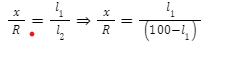 Where x – unknown resistance of given wire, R-resistance in the resistance box, l1-balancing length from left end of the bridge to Jockey.



 Profile
 Settings
 Refer your friends
 Sign out


