 Profile
 Settings
 Refer your friends
 Sign out


Convex Lens
A typical optical lens is made up of two spherical surfaces. We call a lens a biconvex lens or simply a convex lens if those surfaces are curved outwards. The centre of these lenses is thicker, while the corners are thinner.
Furthermore, this type of lens can converge and concentrate a beam of light originating from the outside to a point on the other side. This point is referred to as the focus.
u versus v Graph
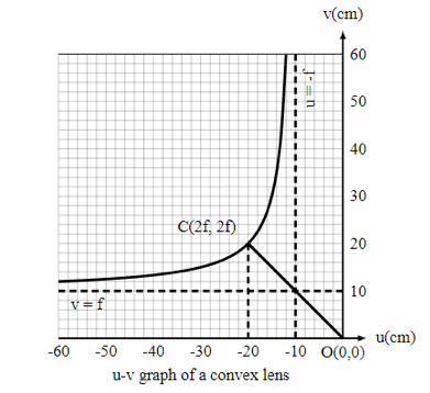
The graph depicts the u versus v graph. The following are the key points in the diagram:
- The graph is hyperbola, with asymptotes at u = -f and v = f, i.e., the image of an object placed at F is formed at infinity, and the image of an object placed at infinity is formed at F.
- The magnitudes of u and v are same at point C, but their signs are opposite, i.e., v = -u = 2f. This is the point where the u-v curve meets the straight line v = -u. When an object is put at a distance of 2f from the pole, its image is generated at the same distance (on the other side).
1/u versus 1/v Graph

The graph of 1/u versus 1/v is displayed in the figure. The graph shows a straight line with a slope of 1 and an intercept of 1f on the v-axis. When an object is put at infinity, 1/u equals zero. The image is created at the focus in this example, therefore v = f.
Concave Mirror
The reflecting surface of a concave mirror, also known as a converging mirror, is sunken inward (away from the incident light). Light is reflected inward by concave mirrors to a single focus point. They’re used to concentrate light. Concave mirrors, unlike convex mirrors, produce a variety of images based on the distance between the item and the mirror.
Converging mirrors collect light that falls on them, diverting parallel incoming rays into a focal. Because the normal to the mirror surface varies at different points on the mirror, light is reflected at varying angles at different spots.
u versus v Graph
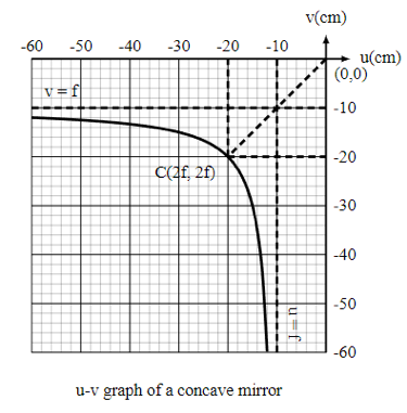
The graph depicts the u versus v graph. The following are the key points in this diagram:
- The graph is hyperbola with asymptotes at u = f and v = f, i.e., the image is created at infinity for the object put at F and at infinity for the object positioned at F.
- At point C, the values of u and v are equal, corresponding to u = v = 2f. This is the point where the u-v curve meets the straight line v = u. This represents the mirror’s curvature’s centre.
1/u versus 1/v Graph
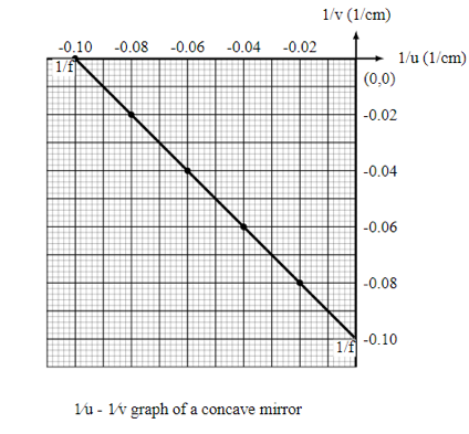
The graph of 1/u versus 1/v is displayed in the figure. The graph is a straight line with a slope of -1 and a 1/v-axis intercept of 1/f. When the object is put at infinity, 1/u equals zero. The image is created at the focus in this example, therefore v = f.
Finding focal length of concave mirror
The focal length of the concave mirror can be obtained in the following ways:
- A concave mirror is a spherical mirror with an inwardly curved reflecting surface that follows the laws of light reflection.
- Light rays from a faraway object can be thought of as being parallel to one another.
- The parallel rays of light meet the point in front of the mirror if the picture generated is actual, inverted, and very small in size.
- The image created by the convex lens is real and may be viewed on a monitor.
- The difference between the primary axis P and the focus F of the concave mirror is denoted by the letter f.
Finding the focal length of convex lens
The following are several methods for determining the focal length of a convex lens:
- The convex lens, also known as the converging lens, is thicker in the middle and thinner at the edges.
- On the other side of the convex lens, the refracted rays from the parallel beam of light converge.
- If the image is captured at the lens’s focus, it will be actual, reversed, and very small.
- The focal length of a lens is defined as the distance between the optical centre and the primary focus.
- As the image created by the lens is actual, it can be obtained on the screen.
Procedure of the u-v method Experiment
- Place the concave mirror on the stand that was provided. Arrange the screen on the table so that it displays the image of the distant item. Using a metre scale, measure the distance between the mirror and the screen. This distance is the mirror’s approximate focal length (f).
- Set the value of u to be between 1.5f and 2.5f. Divide the range into a set of steps that are all the same size.
- Position the mirror in front of a brightly lit object. Place the mirror at the distance u now (which is obtained as 1.5f).
- Place the screen on the table in front of the mirror, so that the reflected image is visible. Adjust the location of the screen to acquire a clear view of the thing while keeping the distance between the object and the mirror fixed. To acquire a precise image position, remove the parallax.
- Measure the distance between the mirror and the object, as well as the distance between the mirror and the screen. Assign these values to the letters u and v, accordingly. Using the formula f = uv/(u+v), find the focal length of the given concave mirror.
- Repeat the experiment with different values of u (up to 2.5f) and record v in the tabular column each time. Calculate the concave mirror’s focal length (f) each time.
- Calculate the mean of all focal lengths to determine the concave mirror’s correct focal length.
- Graphically, the focal length of the mirror may be determined by graphing graphs between u and v, as well as 1/u and 1/v.
Calibration of UV spectrophotometer
In the pharmaceutical industry, UV-Visible spectrophotometers are commonly utilised in the quality control department for analytical purposes. Calibration of the UV-Visible spectrophotometer is performed on a regular basis in order to preserve its accuracy and functioning conditions.
Calibration of UV-Visible spectrophotometer by parts
- Absorption cells
- Control of absorbance
- Photometric linearity
- Limit of stray light
- Resolution power
- Control of Wavelengths
Absorption cells
Fill the cuvette with milli-Q water at 240 nm, and the individual cuvette’s absorbance should not exceed 0.093.
One by one, rotate both cuvettes 180 degrees.
Acceptance criteria: The absorbance difference on rotation of the cuvette should be less than 0.005.
Control of absorbance
For UV region:
Prepared 0.005M sulfuric acid:
Weigh 60.0 mg of potassium dichromate that has been dried to a consistent weight at 130°C in 1000.0ml and dissolved in 0.005 M sulphuric acid with precision.
Using 0.005 M sulphuric acid as a blank, measure the absorbance at 235 nm, 257 nm, 313 nm, and 350 nm.
For visible region:
60.0 mg potassium dichromate, dried to constant weight at 130°C and transferred to a 100.0 ml volumetric flask, dissolved in 0.005 M sulphuric acid
Using 0.005M sulphuric acid as a blank, measure the absorbance at 430 nm.
Photometric Linearity:
In a 50 ml volumetric flask, dissolve 50 mg potassium dichromate in 0.005 M sulphuric acid.
Additionally, dilute the aforementioned solution as follows:
100 ml = 1 millilitre
100 ml x 2 millilitre
100 ml x 3 millilitre
100 ml x 4 millilitre
100 ml x 5 millilitre
At wavelengths of 235,257, 313 and 350 nm, take three consecutive readings of each dilution.
Acceptance criteria: With a mean value of 0.999 for each wavelength.
Limit of stray light
Using water as a blank, record the absorbance of a 1.2 percent potassium chloride solution in water at 200 nm.
Acceptance criteria: The absorbance should be at least 2.0.
Resolution power
At 250nm to 300nm, record the spectra of a 0.02 percent v/v toluene in hexane solution.
Acceptance criteria: The ratio of maximum absorbance at 269 nm to minimum absorbance at around 266 nm should not be less than 1.5.
Control of Wavelengths
To make a 4.0 percent w/v holmium oxide solution, dissolve 1.0 g of holmium oxide in.1.4M perchloric acid in 25 mL.
Using 1.4 M perchloric acid as a reference solution, record the spectrum of holmium perchlorate solution from 200 nm to 600 nm.
Wavelength | Maximum Tolerance |
241.14 | 240.15 to 242.15 |
287.15 | 286.15 to 288.15 |
361.50 | 360.50 to 362.50 |
536.30 | 533.30 to 539.30 |
Conclusion
A typical optical lens is made up of two spherical surfaces. We call a lens a biconvex lens or simply a convex lens if those surfaces are curved outwards. The centre of these lenses is thicker, while the corners are thinner. Furthermore, this type of lens can converge and concentrate a beam of light originating from the outside to a point on the other side. This point is referred to as the focus.
The reflecting surface of a concave mirror, also known as a converging mirror, is sunken inward (away from the incident light). Light is reflected inward by concave mirrors to a single focus point. They’re used to concentrate light. Concave mirrors, unlike convex mirrors, produce a variety of images based on the distance between the item and the mirror. Converging mirrors collect light that falls on them, diverting parallel incoming rays into a focal. Because the normal to the mirror surface varies at different points on the mirror, light is reflected at varying angles at different spots.


