 Profile
 Settings
 Refer your friends
 Sign out


The combination of capacitors can be reached through several methods. The combination is correlated with the battery in order to apply the potential difference or V and to charge the different plates, or Q. The equivalent capacitance of the combination of two points can be defined in the following way –
C = Q / V.
Two combination methods are used frequently: parallel combination and series combination.
The Parallel Combination of Capacitors
If the capacitors have been connected in a parallel way, the potential difference that comes between V across each of the connectors will be the same. The charge of C1, C2 differs from Q1 and Q2. Thus, the total amount of charge of Q can be described as follows:
Q = Q1 + Q2
Q = C1V + C2V Q / V = C1 + C2
The equivalent capacitance that lies between point a and point b will be C = C1 + C2.
The charge of the capacitors can be described as follows:
Q1 = C1 / (C1 + C2) Q, and
Q2 = C2 / (C1 + C2) Q.
If there are more than just two capacitors, then it will be: C = C1 + C2 + C3 + C4 + C5 + …
The Series of Combination of Capacitors
In the case that the capacitors have been connected in a series form, then the magnitude of a charge Q that falls on each one of the capacitors remains the same. Then the potential difference between C1 and C2 differs from V1 and V2. Thus, the potential difference between each combination is as follows: V = V1 + V2
V = Q / C1 + Q / C2 and V / Q = 1 / C1 + 1 / C2
The ratio of Q / V is known as the equivalent capacitance between C and point a and point b.
Equivalent capacitance of C can be reached by the formula: 1 / C = 1 / C1 + 1 / C2
The potential difference that lies across C1 and C2 is V1 and V2, mentioned as follows:
V1 = C2 / (C1 + C2) and V2 = C1 / (C1 + C2) V
In the case that there are more than just two capacitors, then the relation of combination of capacitors examples will be:
1 / C = 1 / C1 + 1 / C2 + 1 / C3 + 1 / C4 + ….
Important points that you must keep in mind:
- When the N capacitors, which are identical in capacitance with C, are connected in a series form, then the effective capacitance will be C / N.
- When the N capacitors, which are identical in capacitance with C, are connected in parallel form, then the effective capacitance will be CN.
Problems Based on the Combination of Capacitors
Problem 1: Two capacitors that have the capacitance C1 = 6 μ F and C2 = 3 μ F have been connected to each other in a series form, and across from a cell that has emf 18 V. Now you have to calculate –
- The capacitance that is equivalent between the two
- The potential difference that will lie across each of the capacitors
- The amount of charge that each capacitor will have
Solution
- 1 / C = 1 / C1 + 1 / C2 – C = (C1 C2) / (C1 C2) = (6 * 3) / (6 + 3) = 2 μ F
- V1 = C1 / (C1 + C2) V = 3 / (6 + 3) * 18 = 6 volts
V2 = C1 / (C1 + C2) * V = 6 / (6 + 3) * 18 = 12 volts
- Q1 = Q2 = C1 V1 = C2 V2 = CV
Thus, each of the capacitors had a charge of = Ceq V = 2 μ F x 1 8 volts = 36 μ C.
In the problem mentioned above, you will be able to observe that the tiniest capacitor has in itself the biggest potential difference across from it.
Problem 2: Search for an equivalent capacitance that lies between point A and point B, when the capacitance of every one of the capacitors is at 2 μ F.
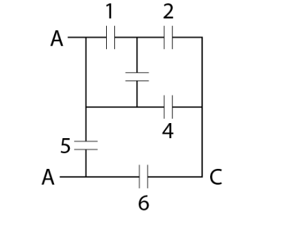
Solution
For the system given above, we can see that points 1 and 2 lie in parallel, whereas point number 5 has been connected between point A and point B. Thus, they can be represented in the following manner:
- Since points 1 and 3 lie parallelly, the effective capacitance of the two will be 4 μ F.
- Since 4 μF and 2 μF lie in a series form, the effective capacitance of the two can be taken at 4 / 3 μF.
- Since 4 / 3 μF and 2 μF lie in a parallel form, the effective capacitance of the two can be taken at 10 / 3 μF.
- Since 10 / 3 μF and 2 μF lie in a series form, the effective capacitance of the two can be taken at 5 / 4 μF.
- Since 5 / 4 μF and 2 μF lie in a parallel form, the effective capacitance of the two can be taken at 13 / 4 μF.
Thus, the final equivalent capacitance of the given system portrayed in the image is 13 / 4 μF.
Conclusion
The combination of capacitors can be reached through several methods. In a series of combinations of capacitors, the capacitors will all have the same charge, that is, the result of the capacitance of the series combination will be C = Q / V. If the capacitors have been connected in a parallel way, the potential difference that comes between V across each of the connectors will be the same.


