 Profile
 Settings
 Refer your friends
 Sign out


The logic gate can be described as a device that functions as a building element to digital circuits. They carry out logical tasks, which are the foundation of digital circuits. Most electronic devices are equipped with at least one logic gate within their circuits. For instance, logic gates can be employed in technology like tablets, smartphones or inside memory devices.
In the system, logic gates decide the function by analysing a mix of digital signals that come through its outputs. Most of these logic gates come with two inputs and one output.
Logic gates are built-in Boolean algebra. At any time, each terminal is one of two binary states, true or false. False indicates 0, and true is 1. The binary output can vary depending on the type of logic gate utilised and the number of inputs used. The logic gate could be considered an electrical switch where the output is on, that is 1, while at another position, the output is off, which is at 0. Logic gates are typically used as integrated circuits (IC).
In this Logic gates (OR, AND, NOT, NAND and NOR) study material, we will learn about the basic logic gates.
Basic logic gates
There are seven logic gates: AND, OR, XOR, NOT, NAND, NOR, and XNOR. Look at study material notes on Logic gates (OR, AND, NOT, NAND and NOR).
AND
The AND gate has got its name because if 0 is referred to as “false” while 1 is described as “true,” the gate operates in the same manner as the logic “and” operator. The following table and illustration have the circuit symbol and the logic configurations for and gate.
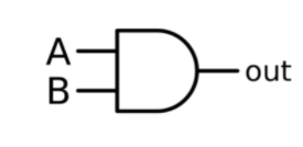
Truth table
Input | Output | |
A | B | Y |
1 | 1 | 1 |
1 | 0 | 0 |
0 | 1 | 0 |
0 | 0 | 0 |
The input terminals appear on the left in the diagram, while an output terminal can be found on the right. This output will be “true” when both inputs match “true.” If not, the output will be “false.” This means that the output is only 1 when inputs one and two are both 1.
OR
The OR gate is named because it performs similarly to the logic operator “or.” Its output will be “true” when either or both inputs match “true.” When both inputs read “false,” the output is “false.” For the output to be one at a minimum, input one or two must be 1.

Truth table
Input | Output | |
A | B | Y |
0 | 0 | 0 |
0 | 1 | 1 |
1 | 0 | 1 |
1 | 1 | 1 |
XOR
The XOR (exclusive-OR) gate functions the same way as the logic “either/or.” This output can be described as “true” when one (but not both) of the inputs are “true.” It is “false” when the inputs of both are “false” or when the inputs of both are “true.” Another approach to the circuit is that the output will be 1 when the inputs differ. However, it is 0 if both inputs are identical.

Truth table
Input | Output | |
A | B | Y |
0 | 0 | 0 |
0 | 1 | 1 |
1 | 0 | 1 |
1 | 1 | 0 |
NOT
A logical inverter is sometimes called a NOT gate to distinguish it from other electronic inverter devices. It has one input. The logic is reversed. If the input is one, the output is 0. If the input value is 0, the output will be 1.
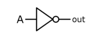
Truth table
Input | Output |
A | Y |
0 | 1 |
1 | 0 |
NAND
NAND gate is a universal gate. The NAND gate functions like an AND gate that is followed by a NOT gate. It works in the same way as the logic operation “and” and is followed by negation. Its output will be “false” when the inputs are both “true.” In other cases, the output will be “true.”

Truth table
Input | Output | |
A | B | Y |
0 | 0 | 1 |
0 | 1 | 1 |
1 | 0 | 1 |
1 | 1 | 0 |
NOR
A NOR gate, a universal gate, can be described as a combination of an OR gate that is followed by an inverter. The output of the gate is “true” when each input is “false.” If not, the output will be “false.”
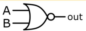
Truth table
Input | Output | |
A | B | Y |
0 | 0 | 1 |
0 | 1 | 0 |
1 | 0 | 0 |
1 | 1 | 0 |
XNOR
The XNOR (exclusive-NOR) gate is an XOR gate with an inverter at the end. The output of the gate is “true” when both inputs are identical and “false” when the inputs differ.

Truth table
Input | Output | |
A | B | Y |
0 | 0 | 1 |
0 | 1 | 0 |
1 | 0 | 0 |
1 | 1 | 1 |
Complex operations can be carried out with the help of these gates. In theory, there is no limit on the number of gates that could be combined within a single device. In reality, however, the limit is set on the number of gates that could be packed into one physical space. Digital ICs can have a range of logic gates. You will find digital devices that are of the best speed and can involve more complicated operations as the technology of IC advances.
Composition of Logic Gates
In these study material notes on Logic gates (OR. AND. NOT. NAND and NOR), we will now learn the basic composition of logic gates.
Various voltage levels express high or low binary conditions. The state of the logic of the terminal may be and usually does frequently change while the circuit is processing data. In most logic gates, there is a low-state at around zero voltage (0 V), and the state of high is around five Volts positive (+5 V).
Logic gates are made out of resistors and transistors, or diodes. Resistors are typically used as pull-up and pull-down resistors. Pull-up and pull-down resistors can be employed when unused logic gate inputs are connected to the logic level 1 or 0. This will prevent any incorrect change of the gate. Pull-up resistors are connected Vcc (+5V), and pull-down resistors connect to the ground (0 V).
Logic gates that are commonly used include the TTL as well as CMO. Transistor-Transistor Logic or TTL, ICs will use Bipolar junction transistors – PNP and NPN type. Complementary Metal Oxide Silicon ICs (CMOS) are made of JFET kind of Field-Effect Transistors and MOSFET. TTL IC’s are typically identified with the name 7400 series. On the other hand, CMOS ICs can be identified with the 4000 series.
Application Of Logic Gates
Logic gates come with a wide range of potential applications. However, they are mostly based on their operations method as well as their truth table. The most basic logic gates can be used in circuits like burglar alarms with light activation, automated watering system, push-button locks, safety thermostats, and other electronic equipment.
One of the main advantages is that the logic gates are utilised in various combinations when the processes are advanced. Within electronic integrated circuits (ICs), we can see a range of logic gate area units.
Conclusion
Logic gates are a crucial concept to consider when studying electronics. These are significant digital devices that are constructed around the Boolean function. Logic gates perform logical operations on the binary input of single or multiple sources and provide a single binary output. In simple terms, logic gates comprise the electronic circuits that are part of the digital system, and they come in 7 types – AND, OR, XOR, NOT, NAND, NOR and XNOR.


