It is generally agreed that the total distance between an atom’s nucleus and the outermost orbital of an electron is referred to as the atomic radius. In simpler terms, it can be defined as something akin to the radius of a circle, where the nucleus is located in the centre of the circle and the outer border of the circle represents the electron’s outermost orbital. As you begin to move across or down the periodic table, you will see trends that will help you understand how atomic radii vary.
When an atom has an effective nuclear charge (Z), it means that the valence electron is feeling a net positive charge on its surface. A small amount of positive charge is shielded by the core electrons, thus the valence electron is not affected by the total amount of positive charge. You can get a more in-depth explanation of shielding and effective nuclear charge here. The atomic size of an atom is substantially influenced by the Z factor. As a result, as the value of Z drops, the atomic radius increases as a result of increased screening of electrons away from the nucleus, which reduces the attraction between the nucleus and electron. Given that Z lowers as one moves down a group and from right to left across the periodic table, it follows that the atomic radius will rise as one moves down a group and from right to left across the table.
Atomic radii are the diameters of solitary, electrically-neutral atoms that are unaffected by the bonding topologies that hold them together. Because electrons are filling outer electron shells as one progresses downwards in the Periodic Table of the Elements, the average atomic size increases as one moves down the Periodic Table. On the other hand, as one proceeds over the Periodic Table from left to right, the atomic radius of the atoms decreases. Despite the fact that more electrons are being added to atoms, they are all located at approximately the same distance from the nucleus; thus, the increasing nuclear charge “pulls” the electron clouds inwards, resulting in decreased atomic radii.
Covalent Radii: The covalent radius is a measure of the size of an atom that is a component of a single covalent bond in an element. Picometres (pm) or angstroms (Å) are the most often used units of measurement, with one angstrom equalling 100 picometres.
Van-der Waals Radii: The Van der Waals radius, abbreviated as rw, of an atom is the radius of an imaginary hard sphere that represents the distance between two atoms that are closest to one another. It was given this name in honour of Johannes Diderik van der Waals, winner of the 1910 Nobel Prize in Physics, because he was the first to recognise that atoms were more than just points and to demonstrate the physical consequences of their size through the Van der Waals equation of state, which is named after him.
Atomic-Ionic Radii: In ionic crystal structures, the ionic radius, abbreviated rion, is the radius of a monatomic ion, which is defined as the radius of the ion. The fact that neither atoms nor ions have sharp boundaries is not taken into consideration, and they are considered as if they were hard spheres with radiuses that are such that the sum of the ionic radii of the cation and anion gives the distance between the ions in a crystal lattice Ionic radii are commonly expressed in either picometers (pm) or angstroms, with 1 angstrom equal to 100 picometers (pm).
A solid element’s atomic radius is half of the distance between the nuclei of identically neighbouring atoms when the element is in its solid state. Rather than having a hard spherical boundary, an atom can be thought of as a tiny, densely packed positive nucleus surrounded by an equally dense but diffusely packed negative cloud of electrons. Because of the different types of chemical bonds that can be formed between atoms, atomic radius values vary (metallic, ionic, or covalent bond). As in the case of sodium chloride, when the atoms next to each other are not identical, a portion of the observed distance between them is allocated to one type of atom and the remainder to the other type of atom.
It is more than twice as large than the ionic radius of sodium found in the compound sodium chloride because of the metallic radius of sodium atoms linked together in a chunk of sodium metal. Each sodium atom in sodium chloride has lost one electron, resulting in the formation of a sodium ion (charged atom) with a unit positive charge. Each chlorine atom, on the other hand, has received one electron, resulting in the formation of a chloride ion with a unit negative charge. The ionic radius of chlorine is roughly twice as large as the radius of a neutral chlorine atom, indicating that chlorine is a strong ion. Covalent bonds include the bond between a pair of chlorine atoms in a chlorine molecule and the bond between the carbon atoms in a diamond, to name a couple of examples. For situations like these and others like it, the atomic radius is referred to as the covalent radius.
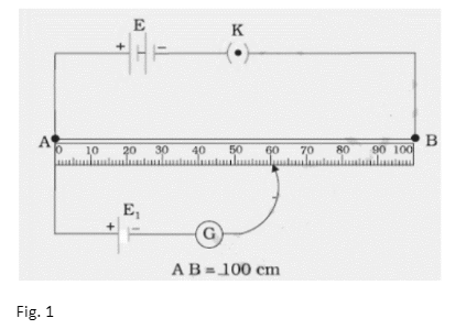
We can only measure the potential difference between the two terminals of a cell using a voltmeter, but we can determine the value of the emf of a cell with a potentiometer.
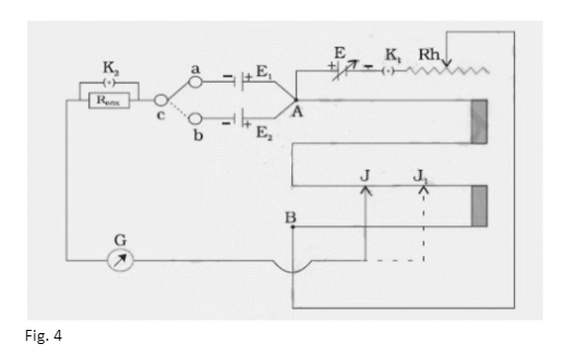
The positive terminals of the two primary cells whose emfs are to be compared are linked in the circuit to the end A of the potentiometer wire AB, and their negative terminals are connected to a galvanometer via a two-way key a, b, c. The galvanometer’s other end is linked to a jockey J.
In the circuit between the two-way key and the galvanometer G, a resistance box, RBOX , is also connected with a key across its terminals, as shown in Fig. 4. With the help of the two-way key a, b, c, the two primary cells with emfs E1 and E2 are connected in turn to the sliding contact J through the galvanometer G.
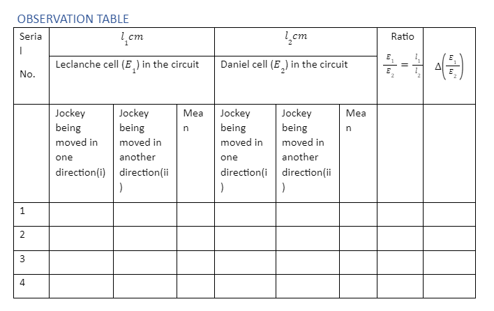
Using the battery E and the rheostat Rh in series across the ends of the wire AB, a steady potential difference may be maintained, with the end A being at a higher potential than the end B. It’s important to remember that emf E is greater than emf E1 and emf E1 greater than emf E2. To bring cell E1 into the circuit, close the gap ‘a c’ in the two-way key. To get null deflection in the galvanometer, slide the jockey on the potentiometer wire. Allow it to happen at J. Make a note of AJ’s length as l1 cm . Similarly, close the gap ‘b c’ and achieve the null point J by sliding the jockey down the wire to bring E2 into the circuit.
Take note of the length AJ1 as l2 cm.
When a constant current flows through a wire of uniform thickness and material, the potential difference between any two spots on it is directly proportional to the length of the wire between the points, according to the principle of the potentiometer.
Thus,
V∝l
V=φl
Here, = potential gradient
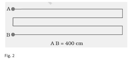
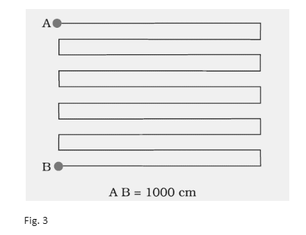
To reduce , the length of the potentiometer wire is increased. The potentiometer becomes more sensitive and accurate when the value of is reduced.
In case of two cells we have
E1=φl1
E2=φl2
Here,
E1& E2= emf of the two cells
l1& l2 = Balancing lengths when E1& E2 are connected to the circuit
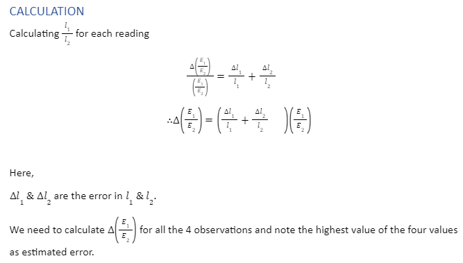
E1/E2 = φl1/ φl2 =l1 / l2
The electric potential created by an electrochemical cell or by changing the magnetic field is referred to as electromotive force, or EMF. Electromotive force is frequently abbreviated as EMF. A generator or a battery is used to convert energy from one form to another. In these devices, one terminal becomes positively charged, while the other becomes negatively charged. An electromotive force is work done on a unit electric charge because of this. In 1830, English physicist Michael Faraday proposed the concept of emf for the first time. Volts is the SI unit for emf measurement. It is denoted by the symbol .
 Profile
 Settings
 Refer your friends
 Sign out