Profile
 Settings
 Refer your friends
 Sign out


Parallel plate capacitors are capacitors with electrodes and insulating material which are arranged in a parallel (dielectric) pattern. The electrodes are two conductive plates. In between there is a dielectric. For plates, this acts as a divider.
Parallel Plate
The two plates of the parallel plate capacitor are similar in size. They are connected to the power supply. The plate is attached to the positive terminal of the battery and receives a positive charge. The plate is attached to the negative terminal of the battery and receives a negative charge. The charges are trapped in the capacitor plates by attraction.
Principle of Parallel Plate Capacitor
A parallel plate capacitor consists of two parallel conductive metal plates which are separated by a dielectric material placed in the middle. If there is a defined potential difference between the two plates, an electrostatic field distribution is created between the plates. There is a uniform distribution of electric field between the two plates. Because of the edge effect, the electric field lines curve and diverge at the edge of the capacitor. Parallel plate capacitor is the simplest capacitor.
Capacitance
Capacitance is defined as the ratio of change in the electric charge of a system to the change in the electric potential of that charge.
The conducting plates have some charges q1 and q2 (generally when one plate has +q then the other plate has -q charge). The electric field which lies in the region between the plates depends on the charge given to the conducting plates. We also know the potential difference (V) is proportional to the electric field so we conclude that,
Q∝V
Q=CV
C=Q/V
Here,
Q =charge
V =potential difference
C = Capacitance
Depending on the use of the capacitor, the capacitance of the capacitor is fixed or variable. From the equation of capacitance, we see that ‘C’ depends on charge and voltage. Capacitance actually depends on the shape and size of the capacitor and also the insulator used between the conductive plates.
Standard Units of Capacitance
The standard unit of capacitance is Farad. But Farad is a big unit for practical purposes. Therefore, capacitance is generally measured in the sub units of Farads like microfarads (µF) or pico-farads (pF).
Mostly electrical and electronic applications are covered by the following standard units of capacitance (SI) which makes the calculations easy.
1 mF (millifarad) = 10-3F
1 F (microfarad) = 10-6F
1 nF (nanofarad) = 10-9F
1 pF (picofarad) = 10-12F
Capacitance of a Parallel Plate Capacitor
The parallel plate capacitor has two similar conducting plates and these two plates have a surface area A and distance between them is d. Charge Q is stored by the plates when voltage V is applied to the plates.
The force between the charges increases with the charge values and decreases with the separation distance. When the plates are larger, they store more charge. Therefore, the value of C is larger for a big value of A. The closer the plates are, the greater the attraction of opposite charges on them. Hence C is larger for smaller d.
Capacitance of a Parallel Plate Capacitor without dielectric
Formula for the charge density on the plates is
σ=Q/A
Here,
σ= Charge density
Q =charge
A = area
When the separation distance (d) is small then the electric field between the plates is uniform and the magnitude is given as
E=σ/Σ0
When the electric field between the plates becomes uniform then the potential difference between the plates is

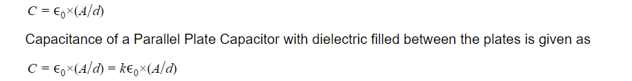
Capacitance of a Parallel Plate Capacitor with dielectric filled between the plates
The charges are shielded on the two plates by the small dipole moment of the material. As a result of this, the impact of the dielectric substance are changes which are put between the two plates. The permeability of a material is represented by the relative permeability k.
The capacitance of the parallel plate when dielectric is filled is given as
Capacitance of a parallel plate capacitor is increased by putting a dielectric between the two plates and the value of permeability k is more than 1 (one).
Factors Affecting the Capacitance
Capacitance depends on the shape and size of the conductor.
Capacitance also depends on the medium between the two conductors.
Capacitance is affected by the presence of other conductors close to it.
Conclusion
Parallel plate capacitors are capacitors with electrodes and insulating material which are arranged in a parallel (dielectric) pattern.
Capacitance is defined as the ratio of change in the electric charge of a system to the change in the electric potential of that charge.
Capacitance actually depends on the shape and size of the capacitor and also the insulator used between the conductive plates.
The standard unit of capacitance is Farad.
Capacitance of a Parallel Plate Capacitor without dielectric is given as