Some circuits are powered by an alternating current or alternating voltage. Such circuits are known as alternating current (AC) circuits. Voltage or current that is alternately altered about a mean value and reversed in direction is known as alternating voltage or current.
Capacitance is charge stored on its plate. On applying AC current a capacitor will charge alternately and discharge at a frequency of the AC current supplied. During the transition from the positive to the negative half cycle of the supply voltage or vice versa at points 0o and 180o along the sine wave, the proportionality of charging current is directly proportional to the amount of change in voltage across the plates.
DC vs AC
- The continuous flow of electrons in a certain direction or forward occurs in DC. AC is the discontinuous flow of electrons that changes direction periodically. When it goes from negative to positive, this power switch also changes voltage values.
- DC and AC are different from generation to generation and distribution in many ways, the most important being the direction of the flow of electrical energy.
- Owing to the absence of sinusoidal waveform function for the supply, the voltage and current are constant over time in DC circuits. AC circuits, however, consistently change their current, voltage, and power output.
- As a result, power cannot be calculated in AC circuits in the same way as before. Nonetheless, we can assume that power equals amperes (i) multiplied by voltage (v).
Passive components in AC circuits
- A resistor’s resistance (R) remains the same whether it is in a DC or AC circuit; capacitance is written as “C”. Inductance is another term for volume, depicted by “L”. Zero inductance is written as L = 0, and infinite capacitance as C = ∞. Such traits are always an indication of a pure resistor.
- The resistance level of all the resistors in an AC/DC circuit is the same.
- The phase and current voltages of a full-resistive circuit are always the same, so we can add voltage to current power to get the power consumed at any given time.
- In contrast, capacitors and inductors have a reaction resistance, referred to as XL and XC. In addition to inhibiting the flow of current, this reaction has a variable value, unlike a resistor with a fixed resistance value.
- An inductor’s reaction value depends on the amount of power it receives as well as its DC value.
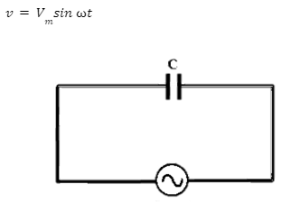
AC circuit containing only a capacitor
An alternating voltage source is connected across a capacitance C capacitor. An alternating voltage is given by the following:

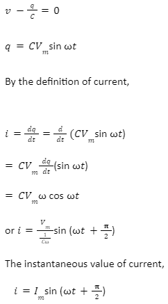
In Kirchoff’s loop rule, if “q” is the charge on the capacitor at that instant, the electromotive force across the capacitor is q/C.

where [Vm] / [1/Cω] = Im ,which is alternating current’s peak value. According to equations 4.49 and 4.50, current leads to applied voltage by π/2 in capacitive circuits.
Capacitive reactance XC
The peak value of current Im is given by Im = [Vm] / [1/Cω]. Comparing the equation with Im = Vm/R from the resistive circuit, the quantity 1/ Cω plays the same role as the resistance R in the resistive circuit. This is called capacitive reactance (XC), or the reactance offered by the capacitor. It is measured in ohm.

Hence, a capacitive circuit provides a constant resistance to the steady current, which is why the constant current cannot flow through the capacitor.
Conclusion
Capacitance is charge stored on its plate. On applying AC current a capacitor will charge alternately and discharge at a frequency of the AC current supplied. The peak value of current Im is given by Im = [Vm] / [1/Cω]. Comparing the equation with Im = Vm/R from the resistive circuit, the quantity 1/ Cω plays the same role as the resistance R in the resistive circuit. This is called capacitive reactance (XC), or the reactance offered by the capacitor. It is measured in ohm. The expression for the reactance of a capacitor is Xc = 1C. The phase and current voltages of a full-resistive circuit are always the same, so we can add voltage to current power to get the power consumed at any given time.

Phasor diagram and wave diagram for AC circuit containing capacitor only
 Profile
 Settings
 Refer your friends
 Sign out


