What Is the Principle of DC Generator?
A DC generator is an electromechanical power conversion tool that converts mechanical power into DC electric power through the system of electromagnetic induction.
DC mills function at the precept of electromagnetic induction, H. When the magnetic flux connecting the conductor changes, the EMF is guided to the conductor. DC mills have subject windings and armature windings.
The electromotive pressure precipitated withinside the armature winding of a DC generator is AC, that’s transformed to DC with the aid of using a commutator connected to the generator shaft. The armature windings of the DC generator are placed at the rotor and the sector windings are placed at the stator.
Construction of DC Generator

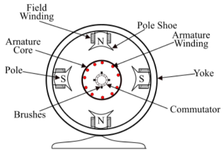
The outer body of the DC generator is a rolled metal perforated cylinder called a cast or yoke.
Magnetic Stand Unit: The magnetic stand unit of the DC generator is the desk designated part of the unit. Generates the number one magnetic liquidity in the generator. Includes a number of pole cores bolted to the yoke and windings wound around the pole center armature center.
The DC generator’s armature center is located on the shaft and rotates maximally around nearby poles. There are slots on the outer surface, and armature conductors are inserted into these slots. The anchor package contains medium-strength iron fins that have been removed and firmly secured. Armature winding the insulating conductor is located in the central slot of the armature. The connections are attached correctly.
This association of related conductors is known as armature winding. Commutator The commutator is a mechanical commutator that converts ACEM generated with the useful resource of using real armature windings into the maximum DC voltage of the brush load terminals. The brush is attached to the commutator and helps to collect from the armature windings today. The brush is made of carbon and is backed by the convenient resource of using a metal shape called a broom holder.
 Profile
 Settings
 Refer your friends
 Sign out


