 Profile
 Settings
 Refer your friends
 Sign out


Introduction
PWM (Pulse Width Modulation) is a technique for converting an analogue signal to a single digital bit. A duty cycle and a frequency are the two basic components that describe the nature of a PWM signal.
Pulse width modulation
PWM (pulse-width modulation) or PDM (pulse-duration modulation) is a technique for reducing the average power produced by an electrical signal by splitting it up into discrete parts. The mean value of voltage (and current) provided to the load is managed by rapidly switching on and off the supply and load switches. The total power provided to the load is higher when the switch is on for longer periods of time than when it is off. It is one of the principal methods of decreasing solar panel output to that which can be used by a battery, along with maximum power point tracking (MPPT). PWM is best for running inertial loads like motors, that are less affected by discrete switching due to their inertia.
MECHANISM OF PULSE-WIDTH MODULATION
Pulse-width modulation speed control works by operating the motor with a series of “ON-OFF” pulses and altering the duty cycle of the impulses while maintaining the frequency constant. The motor’s power can be adjusted by adjusting the width of the applied pulses, and hence the average DC voltage applied to the motor terminals.
Formula of PWM:
(Duty÷256)×5v
Types of PWM
PWM approaches can be divided into three categories:
LEAD EDGE MODULATION
The signal’s lead edge is fixed in this approach, while the trailing edge is modulated.
TRAIL EDGE MOUNTAIN
The signal’s lead edge is modified while the trailing edge remains constant.
PHASE CORRECT PWM
The pulse core remains constant, while both of the pulse’s edges are modified.
According to the requirements, all of these methods are widely used in commercial domains.
Frequency
The frequency with which something occurs or repeats over time. In other phrases, the rate at which a vibration produces a wave, such as sound, radio, or light waves, is commonly measured in seconds.
A frequency or period is unique to the control of a single servo. A servo motor anticipates an update every 20 milliseconds with a pulse of 1 to 2 milliseconds. At 50 Hz, this translates to a duty cycle of 5% to 10%. So, if the pulse is 1.5 milliseconds long, the servo motor will be at 90 degrees, 1 milliseconds, 0 degrees, and 2 milliseconds, 180 degrees. In conclusion, we may acquire a full range of motion by updating the servo with a value between 1 and 2 milliseconds.
Frequency of PWM= 1/Time period
Duty cycle
The phrase duty cycle refers to the ratio of ‘on’ time to the regular interval or ‘period’ of time; a low duty cycle equates to low power, as the electricity is turned off for the most of the time. The duty cycle is measured in percent, with 100 percent indicating that the system is completely operational.
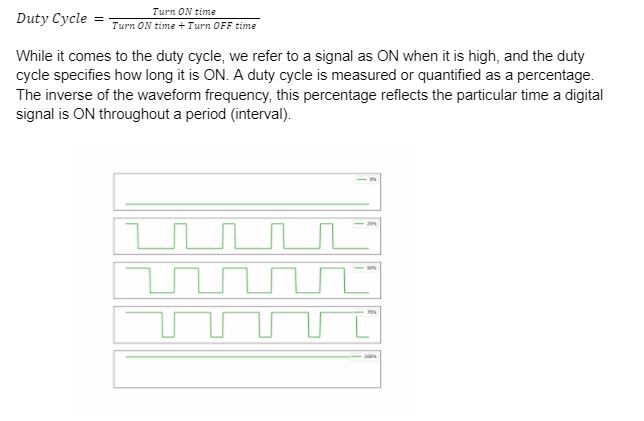
A 50 percent duty cycle means that the high state is active for half of the time and the low state is active for the other half, similar to an ideal square wave. When this ratio exceeds 50%, the logic high signal takes longer than the logic low signal, and conversely. A duty cycle of 100 percent means the signal is always on (full-scale), while a duty cycle of 0 percent means the signal is always off (grounding).
Application of Pulse Width Modulation
Adjust Brightness of Screen using PWM
Controlling the brightness of the screen via PWM does not rely on electricity, but rather on the screen alternating on and off. Whenever the PWM dimming screen is turned on, it does not output light continuously, but it does light up and switch off the screen frequently. If this changes quickly enough, our eyes will perceive it as always on, but with varying brightness dependent on duty cycles. The brighter the screen, the higher the duty cycle.
Other PWM Applications
PWM technique is also used in various applications, such as:
Drive buzzer with different loudness
Provide an analog output
Generate audio signal
Telecommunication: Encode message
GENERAL USAGE OF PWM IN OUR DAILY LIVES
PWM is used in a variety of ways in our daily lives. Adjusting screen brightness, driving a buzzer with varied loudness, controlling the speed of a motor, managing the speed of a servo, providing an analogue output, generating an audio signal, and ding messages in telephony are the most popular uses. PWM can also be employed on Arduino in a variety of ways.
Conclusion
PWM (pulse-width modulation) or PDM (pulse-duration modulation) is a technique for decreasing the average power produced by an electrical signal by splitting it up into discrete parts. The mean value of voltage (and current) provided to the load is managed by rapidly switching on and off the supply and load switches.
The phrase duty cycle refers to the ratio of ‘on’ time to the regular interval or ‘period’ of time; a low duty cycle equates to low power, as the electricity is turned off for the most of the time. The duty cycle is measured in percent, with 100 percent indicating that the system is completely operational.

