The ratio of working power (measured in kW) absorbed by the load to perceived power (measured in amperes,kVA) flowing through the circuit is described as the power factor (PF) of an AC electrical power system. The power factor is a dimensionless number that lies between 1 and-1 in the closed interval.
1 (actually known as “unity”)is the perfect power factor. When the circuit has no reactive power, perceived power (kVA) equals real power (kW). The most efficient loading of the supply is a load with a power factor of 1.
Power Factor
The Power Factor (PF) is a measure of how efficiently power is used. PF is a dimensionless number in an AC (Alternating Current) electrical power system. It is calculated as the proportion of real power flowing to the load to perceived power in the circuit. We want PF to be as near to 1.0 (i.e.100%) as possible in order to get an efficient system.
When the power factor is less than one, the voltage and current are out of phase, which reduces the average product of the two. The capacity of electricity to accomplish work is represented by real power, which is the current product of voltage and current. The product of RMS current and voltage is apparent power. The apparent power may be greater than the true power due to energy contained in the load and returned to the source, or due to a non-linear load that affects the wave pattern of the current pulled from the source. When a device (usually the load) produces power, it flows back to the source, resulting in a negative power factor.
The power factor of a load is increased by power factor correction, which improves the efficiency of the distribution system to which it is connected. A passive network of capacitors or inductors can be used to rectify linear loads with a low power factor (such as induction motors). Non-linear loads, such as rectifiers, cause current to be pulled from the system to be distorted. To overcome the damage and raise the power factor, active or passive power factor correction can be used. Power factor correction devices can be found at a central substation, distributed throughout a distribution system, or embedded into power-consuming equipment.
Power
The rate at which work is completed is referred to as power. It’s all about the work-to-time ratio. The following equation is used to calculate it mathematically:

horsepower is sometimes used to indicate the power delivered by a machine for historical reasons. A horsepower is nearly equals to 750 watts.
Work/time is a formula of power. The equation for power may be expressed as (force×displacement)/time because the expression for work is force×displacement. The expression for power may be simplified as force × velocity because the expression for velocity is displacement/time. This is depicted below:

Hence power=force ×velocity
According to this new equation for power, A powerful system is both strong (large force) and efficient (big velocity.)
Expression for power factor

Watts are used to assess usable power, while VA is used to measure provided power.
Power Factor Values
When the reactive power is zero in a fully resistive circuit, the power factor is 1 (perfect). when the opposite (reactive power) side has zero length, the power triangle appears as a horizontal line.
Since actual power equals zero, the power factor for a completely inductive circuit is 1. when the adjacent (true power) side has zero length, the power triangle will appear as a vertical line.
The same might be argued for a circuit that is entirely capacitive. If the circuit has no dissipative (resistive) components, the actual power must be 0, rendering any power in the circuit entirely reactive.
For a completely capacitive circuit, the power triangle would be a vertical line (pointing down).
Importance of Power Factor
when any power factor less than 1 means that the circuit’s wire must carry more current than would be required with zero reactance in the circuit to deliver the same amount of (actual) power to the resistive load, power factor is a significant consideration in an AC circuit.
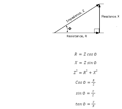
Power factor triangle diagram
An impedance triangle displayed visually the geometric relationship between resistance, reactance, and impedance.

Here, the impedance which is the vector sum of resistance and reactance, has both a magnitude (Z) and a phase angle (∅), which indicates the phase difference between resistance and reactance. Also, as the frequency changes, the triangle will change shape due to differences in reactance (X). Resistance (R) will of course always be constant.
We may expand on this concept by transforming the impedance triangle into a power triangle, which represents the three power elements in an AC circuit. According to Ohm’s Law, power (P) in watts is equal to current squared (12) times resistance in a DC circuit (R). As a result, the three sides of our impedance triangle can be multiplied. The equation given as follows:
Real Power P=I² R Watts (W)
Reactive power Q=I²×Volt-ampere Reactive(VAr)
Apparent Power S=I2 Z Volt-amperes (VA)
Conclusion
The ratio of working power (measured in kW) absorbed by the load to perceived power (measured in amperes,kVA) flowing through the circuit is described as the power factor (PF) of an AC electrical power system. When the power factor is less than one, the voltage and current are out of phase, which reduces the average product of the two. Work/time is a formula of power. An impedance triangle displayed visually the geometric relationship between resistance, reactance, and impedance.
 Profile
 Settings
 Refer your friends
 Sign out


