Since electrical circuits are so complex, it’s impossible to discover the unknown variables using simple Ohm’s rule or series/parallel combination simplification. These circuits are simplified using Kirchhoff’s rules. An electric circuit’s voltages and currents can be determined using such law, whether AC or DC. These principles are extremely helpful in determining the parameters of electrical circuits as elements in an electrical circuit can be linked in a variety of ways.
Kirchhoff’s Laws
The great German physicist Gustav Robert Kirchoff developed these principles in 1847 to define the relationship between current and voltage in an electric circuit. It is Kirchhoff’s Current Law (KCL) and Kirchhoff’s Voltage Law (KVL) that are in question (KCL).
Kirchhoff’s Current Law (KCL)
- Charges cannot be created or destroyed at junctions or nodes; this is the law of conservation of charge.
- According to this law, the sum of algebraic currents is zero at any node.
- As a result, the current entering a node must equalise the sum of the currents exiting it.

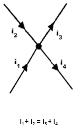
- Currents I1 and I2 are entering the node, whereas I3 and I4 are leaving the node, as indicated in the diagram above. We can write this when we use KCL at the node and assume that the currents entering are positive and the currents leaving are negative.
I1 + I2 + (-I3) + (-I4) = 0
I1 + I2 = I3 + I4
Kirchhoff’s Voltage Law (KVL)
- In a closed path, Kirchhoff’s Voltage Law states that the sum of voltage sources equals the sum of voltage decreases.
- When current goes from a higher potential to a lower potential, it causes a voltage drop in an element.
- A rise occurs in the voltage when the current travels from a lower potential to a higher potential. The energy delivered by the power source must equalise the power vanished by the current in an electric circuit.
- Let us assume that in the circuit, the current flow is clockwise. V1 is positive, IR1 is negative (voltage drop), IR2 is negative (voltage drop), V2 is negative, IR3 is negative (voltage drop), IR4 is negative (voltage drop), V3 is positive, IR5 is negative, and V4 is negative in the above circuit. On applying KVL, we get
V1 + (-IR1) + (-IR2) + (-V2 )+ (-IR3)+ (-IR4) + V3 + (-IR5)+ (-V4) = 0
V1 – IR1 – IR2 – V2 – IR3 – IR4 + V3 – IR5 – V4 = 0
V1 – V2 + V3 – V4 = IR1+ IR2 +IR3 + IR4 + IR5
The KVL is also known as the law of electrical energy conservation because, in a closed circuit, the sum of voltage drops (product of resistance and current) balances the sum of voltage sources.
Applications of Kirchhoff’s Laws
- Applying these rules (direction and value) will allow us to find the unknown voltages, currents, and resistances.
- In the branch approach, currents flowing through a circuit are determined by applying Kirchoff’s Circuit Law at every juncture and KVL in every loop.
- In the branch approach, currents flowing through a circuit are determined by applying KCL at every junction and KVL in every loop.
- Voltage and current can be found using the nodal approach.
- Circuits can be analysed using these rules regardless of their structure or composition.
Kirchhoff’s Circuit Law Sample Problem
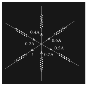
Q. From the given circuit, find the value of I.

Solution
In the circuit, by applying Kirchoff’s rule to point P,
Positive arrows indicate the direction of P, whereas negative arrows point away from P.
Therefore, 0.2A – 0.4A + 0.6A – 0.5A + 0.7A – I = 0
1.5A – 0.9A – I = 0
0.6A – I = 0
I = 0.6 A.
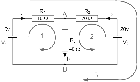
Q. Find the current flowing in the 40Ω Resistor, R3.

There are two nodes, three branches(A and B), and two distinct loops in this circuit.
The equations for using the Kirchoff’s current law (KCL) are as follows:
At node A : I1 + I2 = I3
At node B : I3 = I1 + I2
Using Kirchhoff’s Voltage Law, KVL the equations are given as:
Loop 1 : 10 = R1 I1 + R3 I3 = 10I1 + 40I3
Loop 2 : 20 = R2 I2 + R3 I3 = 20I2 + 40I3
Loop 3 : 10 – 20 = 10I1 – 20I2
We can rewrite the equations as follows because I3 is the sum of I2 and I1
Eq. No 1 : 10 = 10I1 + 40(I1 + I2) = 50I1 + 40I2
Eq. No 2 : 20 = 20I2 + 40(I1 + I2) = 40I1 + 60I2
As a result, we have two simultaneous equations that may be simplified to I1 and I2 values by subtracting them.
The value of I1 -0.143 Amps when I1 is substituted in terms of I2
The value of I2 +0.429 Amps when I2 is substituted in terms of I1
As : I3 = I1 + I2
The current flowing in resistor R3 is given as : -0.143 + 0.429 = 0.286 Amps
And the following formula is used to compute the voltage across the resistor R3:: 0.286 x 40 = 11.44 volts.
Although the first choice of current flow direction was incorrect, the negative sign for I1 suggests that it’s still valid. In reality, the 20v battery is charging the 10v battery.
Conclusion
Kirchoff’s law was formulated by a German physicist Sir Gustav Robert Kirchoff. Using Kirchoff’s laws, one can find the unknown variables in an electrical circuit, as they are quite complicated. The voltages and currents are also determined using these laws, whether AC or DC. There are mainly two laws, Kirchhoff’s Current Law (KCL) and Kirchhoff’s Voltage Law (KVL). In a closed path, Kirchhoff’s Voltage Law implies that the sum of voltage sources equals the sum of voltage decreases. According to Kirchoff’s Current Law, charges cannot be created or destroyed at junctions or nodes, which is also known as the law of conservation of charge. According to this equation, the sum of algebraic currents is zero at any node.
 Profile
 Settings
 Refer your friends
 Sign out


