 Profile
 Settings
 Refer your friends
 Sign out


The capacity of the LCR circuit to tune or resonate is widely recognized. It refers to an electrical circuit that consists of three components: an inductor (L), a capacitor (C), and a resistor (R). In this circuit, the resistor, inductor, and capacitor are connected in series, leading the circuit to have the same amount of current flowing through it. In general, an RLC circuit’s differential equation is analogous to the differential equation of a driven, damped oscillator. Impedance, for example, is employed in the formulation of the LCR circuit equations. Impedance is the resistance associated with the LCR series circuit. It is composed of the resistance given by the inductor, resistor, and capacitor, among other components.
LCR circuit development
Consider the following electrical circuit, which connects an inductor, a capacitor, and a resistor in series. Assume the circuit receives an alternating current (AC) voltage.
The circuit has an inductor (L), a capacitor (C), and a resistor (R), all connected in series.
Assuming the following source voltage values:
Vm = Vm sin (t)
Here,
The symbol Vm represents the amplitude of the applied voltage.
The letter w represents the frequency at which the voltage is administered.
Assume that q is the charge on the linked capacitor, and when Kirchhoff’s loop rule is applied to this circuit, the following conclusion is obtained:
L (dI/dt) + IR + q/C = v
Reactance in LCR Circuit
In an LCR series circuit, the capacitive and inductance reactance have opposing effects. The capacitive reactance causes the current to lead the voltage, whereas the inductance reactance causes the current to lag the voltage. When we combine both in the circuit, the capacitive and inductance reactance difference will be the resulting effect. This is called reactance.
X = XL – XC (or) X = XC – XL

Impedance
Impedance is a property that opposes the flow of electrons in an electrical circuit. It is a combination of both reactance and resistance.
Z represents impedance, which can be determined using the following equation:
Z = √(R2 + (XC – XL)²)
Its metric unit is represented by the symbol (ohm).
Phasor Term of Impedance
X = R + jX
Impedance in LCR Circuit
The combined opposition of both resistance and reactance is called impedance, denoted by Z. The impedance cannot be calculated by adding the resistance and reactance. As it is an AC circuit, the R, C, L will step in and reach maximum values simultaneously.
The larger the reactance than the resistance, the more the phase difference will achieve 90° more. The larger the resistance, the more the phase difference will achieve 0° more nearly.
The resistance and reactance can be found using the construction of a right-angle triangle.
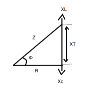
In the triangle above, if XL > XC, the circuit inductively gives a lagging phase angle.
If XC > XL, the circuit is capacitive, giving a leading phase angle.
If XC = XL, the angular frequency at which it occurs is called resonant frequency.
The magnitude of the current depends on the frequency in the LCR circuit. When Z is maximum, I will be minimum.
Impedance, Z = 1 /√ (R² + (L – 1/C)²)
Resonance
Electric circuits, such as the LCR, have the ability to resonate at a specific frequency, known as the resonance frequency, f0. Hertz is the standard unit of measurement for all frequencies. Because it is more technically convenient, the angular frequency 0 is employed in calculations. It is important to understand that angular frequency is measured in radians per second, not hertz. The equation for angular and resonant frequency is as follows:
ω=2πf0
Energy can be stored in both an electric and magnetic field when the capacitor is charged, and the current flows through the inductor device, resulting in resonance. Both of these stored energies may be transferred and oscillatory in nature from one device to the other inside the circuit. When released, a weight on a spring causes an oscillation, which is a mechanical analogy. It should be noted that the analogy between a weight oscillating on a spring and an LCR circuit is not coincidental, as the LCR circuit can be described by the same second-order differential equation that describes the weight oscillation.
For a spring–weight system, friction serves as an approximation to the resistor’s role in a circuit. In the absence of an external force, frictional force will eventually bring an oscillation to a halt. Similar to the LCR circuit, if there is no AC power source in the circuit, the oscillation will be “dampened” (slowed down) by the resistance in the circuit.
The frequency at which the impedance (resistance to the flow of current) of the circuit is at its lowest can be explained as his resonance frequency. In other words, the frequency at which the impedance is purely resistive can be defined as the frequency. Resonance is caused when the inductor and capacitor have equal but opposite phase impedances, which cancel each other out.
Resonant Frequency
The frequency when the amplitude is increased is called the resonant frequency.
ω= 1 /√LC
Example: Swing
Initially, the swing oscillates in natural frequency. When someone pushes the swing forcefully, then the amplitude of the oscillation increases, resulting in resonant frequency.
Resonance of LCR Series Circuit
We know that the amplitude will be maximum at the resonant frequency. Resonance is determined when both the L and C are in the circuit.
The current amplitude is given as Im = ( Vm / Z )
At resonance, Im would be maximum, and Z would be minimum.
Im = ( Vm /√ (R² + ( XC – XL )² )
So , 1/ωC=ωL
R = (1/ √LC ), which is the resonant frequency.
Conclusion
We have discussed that current can be generated by connecting a continuous source of voltage or battery to a resistor. The generated current only travels in one direction and has a fixed amplitude. Generally, the battery’s negative and positive ends are connected. Alternating current is referred to when the direction of the current across a resistor changes on a regular basis.
As we’ve seen, an LCR circuit is often referred to as a tuned or resonant one. An inductor (L), a resistor (R), and a capacitor (C) are all parts of the circuit. The same amount of current passes through the circuit since the resistor, inductor, and capacitor are linked in series. A driven and damped oscillator is analogous to the RLC circuit’s differential equation. The LCR circuit equations are derived from notions like impedance, which are essential. The resistance in the LCR series circuit is referred to as impedance.
