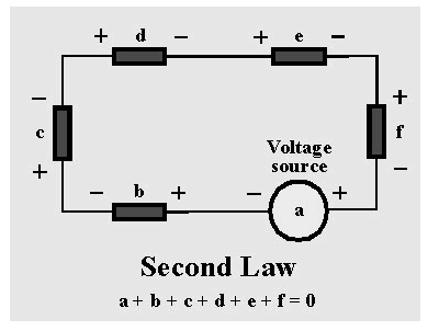
The voltage loss across a circuit is dealt with by Kirchhoff’s second law. It asserts that if the voltage drop at each point of a circuit moves in either a clockwise or counterclockwise direction, the total voltage drop throughout the closed-loop must equal zero. This is the result of electric potential conservation. We’ll come back to this later in the article.They’re commonly used in electrical engineering to determine the current running through each arm of a complex circuit if the voltage drop at each point is known, or to determine the voltage drop at a point in a circuit if the current flowing through the arms of the circuit is known.
Kirchhoff’s second law equation
Kirchhoff’s second law, also known as Kirchhoff’s loop (or mesh) rule, or Kirchhoff’s second rule, asserts that:
Any closed loop’s directed sum of potential differences (voltages) is zero.
The voltage law can be expressed in the same way as Kirchhoff’s current law:

An example can be used to explain the preceding assertion. The amount of labour required to carry a charge to a specific position in the presence of an electric field is known as electric potential. Assume that one of the points in a circuit has a specific potential. The amount of work done in transferring a charge that is resting at that location through the circuit in either a clockwise or counterclockwise direction and finishing at the same point is zero.This is because a point has a fixed potential, and bringing the charge back to it after moving it throughout the circuit has no effect on the charge’s electric potential. If the charge has a different potential at the same spot, it means a single point in the circuit has two separate electric potential values connected with it, which is illogical and impossible.
Kirchhoff’s second law holds true for all of the ordinary circuits we come across in our daily lives. Because electric potential remains the same regardless of the presence of physical circuits, this is also true for imaginary circuits. It’s also quite handy in instances involving static electricity.
Kirchhoff’s second law is not without flaws. It only applies to lumped circuits. Physical qualities that are dispersed across the entire circuit, such as resistance, are localised at a single point in a lumped circuit.
Derivation of kirchhoff’s Voltage law
Consider the following circuit. Using lumped parts, approximate the circuit so that (time-varying) magnetic fields are contained within each component and the field outside the circuit is insignificant. The Maxwell–Faraday equation demonstrates that, based on this assumption:

If each component has a finite volume, the outside region is simply connected, and the electric field in that region is conservative. As a result, we may deduce that for any loop in the circuit:

Pi denotes the routes that run around the outside of each component, from one terminal to the next.
Note that the voltage rise from a to b is defined as follows in this derivation:

However, other methods, such as the Helmholtz decomposition, can be used to define the electric potential (and consequently voltage).
Kirchhoff’s second law circuit diagram

This law is about voltage. For example, the circuit shown above is explained. A voltage source ‘a’ is connected to five passive components with voltage variations, namely b, c, d, e, and f. Because these components are coupled in series, the voltage differences between them add up arithmetically. The voltage across the passive components in a circuit is always equal and opposite to the voltage source, according to the KVL law. As a result, the sum of all voltage differences across all circuit elements is always zero.
a+b+c+d+e+f=0
Terminology Used in DC Circuit Theory
- Circuit:A closed loop conducting channel through which an electrical current flows is referred to as a DC circuit.
- Path:The sources or elements are connected by a single lane.
- Node:A dot denotes a node, which is a connection in a circuit where numerous elements are joined together.
- Branch:A branch is a single or a group of items connected between two nodes, such as resistors or a source.
- Loop:A circuit loop is a closed path in which no circuit element or node is encountered more than once.
- Mesh: A mesh is a single open loop that does not have any components and does not contain any closed paths.
Conclusion
The laws have the benefit of making it simple to calculate unknown voltages and currents. Complex closed-loop circuit analysis and simplification become manageable.Kirchhoff’s principles function under the assumption that the closed-loop has no fluctuating magnetic fields. Under the influence of a fluctuating magnetic field, electric fields and electromotive force can be created, causing Kirchhoff’s rule to be broken.
 Profile
 Settings
 Refer your friends
 Sign out


