In 1820, HC Oersted proved that electric current creates a magnetic field around it. Michael Faraday observed this and believed that if an electric current can create a magnetic field, then a magnetic field can also create a current. In 1831, Faraday showed the world that if a magnet is moved inside a copper coil, a very small electric current is induced in it.
This gave a new direction in the research of magnetism and forces related to it. So, in this article, we will have a detailed discussion about the Magnetic Field and its characteristics, force on a current-carrying conductor, and magnetic field due to a current-carrying wire.
Magnetic Field
The magnetic field can be defined as a measure of the magnetic force that can be observed by interacting particles in a certain space. The magnetic field can arrange the magnetic objects in the direction of the field. For example, Earth’s Magnetic field makes a magnetic needle compass, and other magnetic objects line up in the direction of the field.
Magnetic Field Lines
Magnetic Field Lines are imaginary lines found around a magnet and define the direction and strength of the magnetic field. In a bar magnet, these lines are denser at the poles; hence the magnetic field at the poles will be greater than at the centre.
Characteristics of Magnetic Field Lines
There are several characteristics of Magnetic field lines, and they are as follows –
- Magnetic field lines do not intersect each other in any condition.
- They always take the minimum resistive path to reach the other pole of the magnet.
- The density decreases when they move from a region of higher permeability to lower permeability.
- In a bar magnet, the magnetic field runs from the south pole to the north pole inside the magnet and from the north pole to the south pole outside the magnet.
- The magnetic field density will be decreased when moving away from the poles and vice versa.
- As it possesses both magnitude and direction, the magnetic field is a vector quantity.
- The direction of the magnetic field is tangential to the magnetic field lines.
Magnetic field due to current-carrying wire

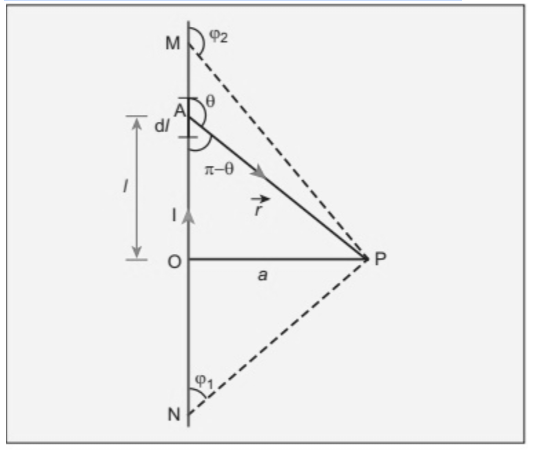
Let us take a long straight wire in which current I is flowing from N to M (see figure above)
Let the length of OP be a. Take a small element of length dl of the straight wire which is at a distance l with respect to point O.
As we already know by biot-savart law –
B→=∫dB→=μ0I/4πdlxr/r².
r is the vector joining the dl element with the point P. Let’s suppose θ is the angle between r and dl. Therefore Magnetic field at P due to dl is
dB→=μ0I/4π.dl/r².sinθ
The magnetic field is making a 90-degree angle with the plane of the paper and going into it. We can find it out by determining the cross product between two vectors dl →and r→
By integrating the equation with defined limits we can find the net magnetic field.
In the triangle OAP
tan(90-θ)=a/l
l=-acotθ and r=a cosec θ
Now on differentiating, we get
dl = a cosec²θdθ
dB→=μ0I/4π(a cosec²θdθ/(a cosec θ)².sinθn∧
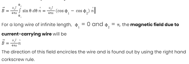
dB→=μ0I/4πa .sinθdθn∧
For small dl length, this is the magnetic field due to current-carrying wire at point P
Since this magnetic field OP is expressed in terms of angular coordinate which is θ
The direction of this field encircles the wire which is denoted by n∧.
Hence, the net magnetic field can be determined by integrating dB by changing the angle from θ = Ø1 to θ = Ø2 is

Force on a Current-Carrying Conductor in Magnetic Field
Since we know that moving current generates a magnetic field around it and behaves like a magnet, a magnet experiences some force when placed in this magnetic field.
In the same way, the magnet also exerts a force on the current-carrying conductor, which Fleming’s left-hand rule can determine.
So let us understand by the following derivation.
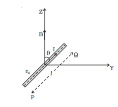
Let’s take a conductor PQ, whose length is l and has a cross-section area A. The conductor is in a uniform magnetic field B that makes an angle θ with the magnetic field and conductor.

Here, the current I is flowing through PQ. Therefore, the electrons will move (drifted) along QP with Vd drift velocity. Let’s take n be the number of electrons per unit volume within the conductor, then-current can be defined as
I→ι = nAvd→eι
When both of the sides are multiplied by the length of the conductor l, we get
Il→ = nAvd→el
And hence the current element be
Il→ = nAvd→el……….(1)
Here the negative sign implies that the direction of current is opposite to the direction of moving electrons (drift velocity)
As we know, the electrons move under the impact of the magnetic field. Therefore, the magnetic Lorentz force experienced by the electron will be
f→=-e(vd→xB→)…………………..(2)
A negative sign means the negative charge carried by the electron
The number of free electrons inside the conductor
N = nAl…………………….(3)
Magnetic force on the free electrons will be
F→=Nf→
Now, by eq(1), (2) and eq (3)
F→ =lI→xB→
Hence, the magnitude of the force exerted is
F = IBl sin θ [ where θ is the angle between current element and B]
Therefore it can be concluded that
- If the current-carrying conductor is placed in the direction of the magnetic field, the force exerted will be Zero ( as θ = 0)
- When the magnetic field and current-carrying conductor are perpendicular to each other, then the exerted force be maximum (θ = 90)
The direction of the force
Fleming’s left-hand rule can find out the direction of the above force.
Also, we can directly use the rules of cross product to find the direction. However, keep in mind that the direction of vector l is along the direction of the current.
Conclusion
We hope that this will have helped you understand this topic even better. You have to think in an analytical way to understand it better. For example, in Fleming’s left-hand rule, try making the shape in your hand to understand it better. The same goes with the magnetic field. Visualise it in your mind to have better conceptual clarity.
 Profile
 Settings
 Refer your friends
 Sign out


