 Profile
 Settings
 Refer your friends
 Sign out


The German physicist Georg Simon Ohm was the first person to study the relationship between resistance, current, and voltage. According to him, resistance is the measure of opposition to the flow of electric current in a circuit. The SI unit of resistance is known as ohm (Ω), after its founder. Examples of resistance can be found in many day-to-day activities, and there are several factors on which the resistance of a conductor may depend. These factors also influence the characteristics of resistance.
The Formula Of Resistance
The formula of resistance which gives the relation between resistance (R), voltage (V), and the current (I) in a conductor is given by:
V = IR
Or
R = V/I
Where
V is the voltage in volts (V)
I is the current in amperes (A)
R is the resistance in ohms (Ω)
Also, consider a conductor where:
L = the length of the conductor
A = the area (cross-sectional) of the conductor
n = the number of free electrons in the conductor (considered per unit volume)
τ (tau) = the relaxation time
⍴ (rho) = the resistivity of the conductor’s material
The resistance of the conductor can thereby be calculated as
R = ⍴ L∕A = m∕ne2τ * L∕A
Derivation: The Formula Of Resistance
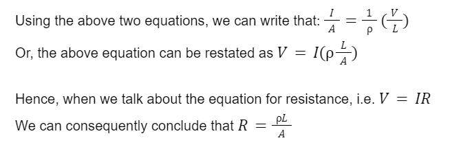
We make use of Ohm’s law to derive the equation for resistance. As per Ohm’s law, the relation between the density vector of current (denoted by J) and the electric field applied is given below.
J=σE=1/σ
σ is the constant of proportionality for the material. It is known as ‘conductivity’.
σ is also the inverse of ⍴, known as the material’s ‘resistivity’.
Further, using the definition for potential difference, we know that: E=V/L
Also, the current that flows through a circuit can be expressed as J=I/A
Characteristics Of Resistance
One of the fundamental elements of Ohm’s law is resistance, which may be found in almost any device that conducts electricity. There are several factors on which the resistance of a conductor may depend. These have been discussed below.
1. The length of a conductor:
Resistance is always directly proportional to the length of the conductor in use, i.e. R∝ L.
For example, a wire with conducting properties and the resistance R is divided into n equal parts.
As a result, the resistance of each component will be R∕n.
2. The cross-sectional area of a conductor:
Resistance is always inversely proportional to the area (cross-sectional) of the conductor in use, i.e. R∝ 1/A.
3. The material of a conductor:
Resistance is dependent on the conductor’s nature of the material, i.e. R∝ 1/n.
For various conductors, the value of n is different.
As a result, the value of resistance (R) also varies.
4. The temperature of a conductor:
Whenever a metallic conductor gets heated, the metal’s atoms vibrate with higher amplitude and frequency about their mean positions. As a result, the number of collisions among all the free electrons and atoms grows.
This phenomenon causes a reduction in the relaxation time of the conductor (τ).
As a result, the value of resistance (R) increases.
Consequently, for a conductor, the Resistance ∝ temperature.
5. The potential difference of a conductor:
The resistance of a conducting body is not unique.
It is determined by the length and cross-sectional area of the conductor.
How the potential difference is applied makes a significant impact.
The Implications of Resistance In Physics
There is one major question that plagues the study of resistance: is it ultimately beneficial or not?
Consider a scenario when we are trying to transmit electric current from one place to another. In this case, resistance is an undesirable factor. Resistance may cause some of the electric energy to be lost and get converted to heat.
However, in our homes and elsewhere, we use resistance effectively with electricity. It is resistance that is responsible for the heat from electric heaters and light given by light bulbs.
One thing to remember is that the resistance of wires small in size is higher. As a result, if the voltage or EMF is strong, a large amount of current flows through smaller wires, heating them.
Sometimes, the heating may be beyond one’s control and even cause a fire or an explosion.
Therefore, it is advisable to make use of resistors in a circuit, to restrict the flow of electric current.
The Concept Of Resistors And Resistances
Resistors, one of the most fundamental components in any electrical circuit, are distinctive components.
Although resistance exists in all materials, resistors are distinct components designed to provide a certain amount of resistance in a circuit.
Resistors are part conductor, part insulator, and are formed of a clay-carbon mixture. They conduct electricity as a result of this, but only with a certain amount of resistance added on to them.
The value of resistance is monitored closely. Four bands of colour are present on most resistors.
The Structure Of Resistance In Series Circuits
A series structure of anything is generally related in some way along a line, a row, or any form of order.
In electronics, a series resistance will indicate that the resistors are all connected in order and that the current can only pass through one passage.
The overall circuit resistance is the sum of individual resistances.
The current that flows through each point in the circuit is the same.
The sum of all individual voltages in the circuit gives the total voltage.
The total resistance (RTotal ) in a series circuit can be calculated using the formula:
RTotal = R1 + R2 +R3
The Structure Of Resistance In Parallel Circuits
Instead of placing multiple resistances in series, there is another way to do it: by placing the resistors parallelly.
The total resistance (RTotal) of the circuit is calculated by adding the reciprocals of all the individual resistances.
The voltage at each point in the circuit is the same.
The total current drawn is the sum of individual current that flows across the circuit.
- The total resistance in a parallel circuit can be calculated using the formula: 1/RTotal = 1/R1 + 1/R2 + 1/R3 + …
Conclusion
The reader may further explore a detailed study on the difference between resistance and resistivity, and static versus differential resistance. Additionally, since resistors are known to oppose the flow of current, a substantial amount of energy is dissipated in the process. This is known as the Joule (Ohmic) heating, an important aspect in the study of resistance. Examples of resistance such as the electric resistance of the human body, air, water, or copper are concepts that can be studied in detail.
