Ray diagrams assist us in tracing the path of light for someone seeing a point on an image of an item. Lines represent the incident and reflected rays with arrows in a ray diagram. It also aids us in determining the direction of travel of light. Rays for the incident and reflected rays are represented on the diagram. Stick figures or arrows are frequently used to represent complex objects like people. It is typical to draw rays for the extreme positions of such things in such instances.
A mirror reflects a surface on which light is reflected to create a real or virtual picture. When you set an object in front of a mirror, it will reflect the identical object to you. The object emits the incident rays, and the reflected rays form the picture. The views are characterised as either natural or virtual based on how light interacts. When light rays unite, an exact picture is made, but virtual pictures are created when light rays appear to diverge from a point.
Concave Mirror: A mirror is created when a hollow spherical is broken into parts, and the exterior surface of each cut component is coated, with the internal surface reflecting light. This type of mirror is known as a concave mirror.
Convex Mirror: If the empty sphere’s cut half is painted from the inside, the sphere’s exterior surface becomes the reflective surface. A convex mirror is a name for this type of mirror.
Ray Diagram Applications
Ray diagrams are handy for establishing and describing why just a piece of an object’s image may be seen from a specific point. The lines of sight employed by the eye to perceive a portion of the image in the mirror are depicted in the ray diagram to the right. The eye can only see the upper section of the picture since the mirror isn’t long enough. The point in line with the line of sight that touches the very bottom of the mirror is the lowest point on the image that the eye can see.
Similarly, ray diagrams may determine and describe what items can be seen when looking into a mirror from a specific place.
The Ray Diagram Rules
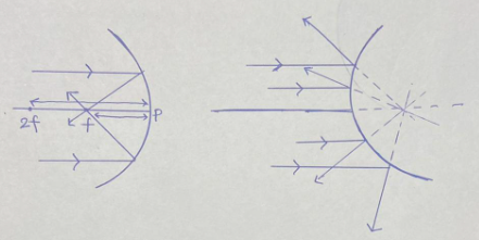
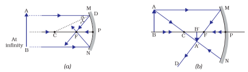
A beam parallel to the main axis will pass through focus after reflection.
After reflection, the light travels through focus in a concave mirror.
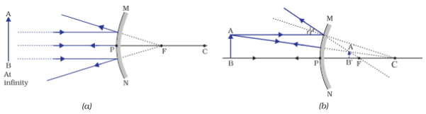
Because the right side is the center of focus of a convex mirror, it looks like the beam passes through the focal point after reflection.
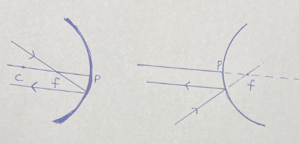
The beam passing through the focus will become parallel to the main axis after reflection.
After reflection, the ray travelling through the focus of a concave mirror becomes parallel to the major axis.
Because the right side is the center of focus of a convex mirror, it looks like the beam passes through the focal point before becoming parallel to the major axis.
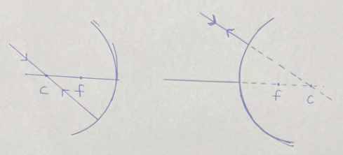
A ray going through the Center of Curvature will return on the alike path after reflection.
In the case of a concave mirror, we can observe that a ray passing through the Center of Curvature returns on the same path.
Because the Center of Curvature is on the right side of a convex mirror, it looks like the ray passes through it and then returns along the same path.
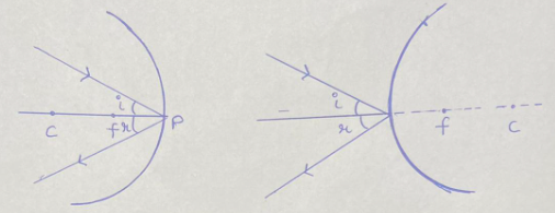
Ray incident at pole reflects at the same angle as the main axis.
If the incident ray to the Pole causes an angle of incidence ‘i’ it will return at an angle of reflection ‘r’ with the primary axis as the normal for both concave and convex mirrors.
Angle of Reflection = Angle of Incidence
Image formation
Ray Diagram of a Convex Mirror
A virtual picture is produced at the focal point when an item is positioned at infinity. When contrasted to the item, the picture will be much reduced.
The virtual image is created between the pole and focus when an item is positioned at a limited distance from the mirror. In comparison to that thing, the picture is much smaller.
Concave Mirror Ray Diagram
An accurate image is produced at the focal point when an item is at infinity. In comparison to the thing, the picture is much smaller.
When the item is positioned beyond the centre of curvature, an authentic image is generated between the focus and the centre of curvature. In comparison to the item, the size will be modest.
When an item or thing is placed in the curvature’s centre, a genuine picture is produced in the curvature’s centre. The picture has the exact dimensions as the thing.
When an item or thing is put between the focus and the curvature, a true picture is formed beyond the centre of curvature. In comparison to the item, the size will be bigger.
When an item is placed in the focus, an exact image is formed at infinity. The picture is substantially more significant than the item focused on.
A virtual picture is generated behind the mirror when an object is put between the pole and the focus. In comparison to the item, the size is more prominent.
Conclusion
So, after reading this post, one will better understand what a ray diagram is and why it is essential in mirrors. One will also learn about the laws of ray diagrams for concave and convex mirrors from the preceding article. Hope you will find the information above to be helpful. Continue to study, and best of luck in achieving your objectives.



 Profile
 Settings
 Refer your friends
 Sign out