Profile
 Settings
 Refer your friends
 Sign out


Digital electronics deals with the detailed study of digital data and codes. These are the industrial electronics that are now usable in the fields of communication and military operations. The coding system in digital electronics makes it more secure and stable. There is a special number system in this study that creates the data for further functioning. The logic gates in digital electronics play an integral role in the circuit system of digital electronics. The study of digital electronics is about the code system which has its design in a manner to send and receive a message in a particular format.
Definition:
Digital electronics are the circuits of the modern era. In the world of electronics two types of signals are present:
- Analog signals- the signals which function in a continuous manner.
- Digital signals- the signals which function in a discrete manner.
Digital electronics follow the binary numbering system as of 0 and 1. The complete data of a logic gate is an electronic circuit which relies on this system itself. There are several apparatus of modern technology which follow this formula for functioning.
Components of digital electronics:
Based on the functioning property the digital system has certain types of components. The complete functioning of digital electronics varies on the basis of these components. There are two types of components in digital electronics. The basic and rapid function under this depends upon the gates in digital electronics. Below are the two important components of digital electronics:
- Active components :
These components turn out to be useful to allow the smooth flow of current in the circuit. This type of component is the active component. Transistors and diodes are common examples of active components in digital circuits.
- Passive components :
These components store the electric energy and change it into the magnetic field as per the requirements. Inductors, capacitors, and insulators are the basic examples of passive components in digital electronics.
Logic gates:
These gates play the most important part in digital electronics. Many of the theories state that logic gates in digital electronics which direct the current and power flow are its building blocks. The digital circuit is all about the input and output of the current flow. The logic gates are the result of the relationship between input and output current. This logic makes the circuit flow in a different way. There are various kinds of logic gates, the only common factor in all the logic gates is that it has only one output. There are positive and negative logic gates in digital electronics and each gate may have more than one output.
The gates in digital electronics are of certain types. The division of these logic gates is on the basis of their functioning and the type of circuits for which they are useful. Here is the description:
AND Gate:
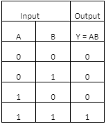
This gate has two or more inputs and ends with a single output which is its ‘logic’, it is one of the basic logic gates in digital electronics. This type of digital circuit takes the input A and B from two or more sources to produce it is logical AND Y. This is the reason this gate is an AND gate.
The above is the logic diagram and truth table of the AND gate. Here A and B are the inputs and Y is the logical AND output. The truth table states all the possible functioning of the circuit if the current passes through the AND gate. Many questions like ic 7408 are used for which logic gate arrives often. The AND gate involves such usage of ICs.
OR Gate:
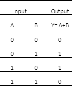
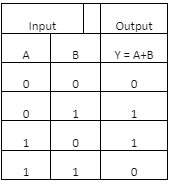
This Gate also has two or more inputs with a single output to produce a logical OR. This gate produces the output in an extra format
The above is the logic diagram and truth table which shows the tendency of the flow of current. The truth table states all the possible output values from the OR gate.

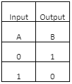
NOT Gate:
This gate is also known as the inverter because it receives a single input and produces a single output. It is an inverter also because it produces the output inverse value of the input received. Here are the logic diagram and the truth table:
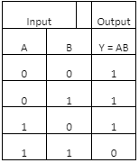
NAND Gate:
This gate is the combination of AND and NOT gate. The gate can have more than two input values and a single output value. It gives the equal result like in AND and NOT gate produces. The truth table and logic diagram are:
NOR Gate:
This gate is the combination of NOT and OR gate and also gives similar results as these two gates give. This works with the same fundamental if two or more input values and a single output.
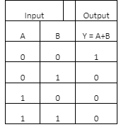
These are the truth table and logic diagram of the NOR gate.
XOR Gate:
This gate works as a subtractor and full and half adder. This is a special gate also known as EX-OR Gate. It can have two or more inputs with one single output.
This is the logic diagram and truth table of the XOR gate.
XNOR Gate:
This gate is useful as a full and half adder and subtractor. This gate mentions the positive and negative logic in digital electronics. It is also known as EX-NOR Gate with two or more inputs and a single output.
The above is the truth table and logic diagram of XNOR Gate.
Advantages of logic gates:
There are many advantages of logic gates that mark their performance in digital electronics. Here are some of them:
- These gates give very quick performance than other components.
- They need the very least amount of energy.
- Never get overworked.
- Bring clear and encrypted data.
Conclusion:
In the present era, digital electronics mark a strong position in each field. Digital electronics work on the simple principle of input and output. They follow the binary format for the flow of current and the gates in digital electronics make it more secure to use it. The present era comes with the need for encryption increasing in each field hence these logic gates perform low maintenance and provide secure logic and data. All the gates can receive the input from various ends but they make sure to provide the output through a single interface. This enhances the security level and trust for digital electronics.