Capacitors have various applications–from filtering static from radio reception to storing energy in defibrillators. Commercial capacitors typically contain two conducting components that are close but do not touch each other. Between the two plates, most of the time, a dielectric is employed. The battery potential transports a slight charge from the positive plate to the negative plate when the battery terminals are connected to an initially uncharged capacitor. When two or more capacitors in a series are connected, the overall impact is that of a single equivalent capacitor in relation to the sum total of the individual capacitors’ plate spacing.
In other words, a capacitor is neutral, but it charges and resides on opposite plates.
Capacitors in a Series
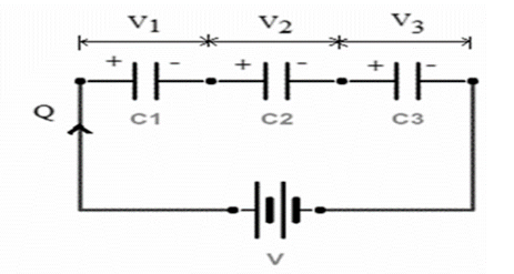
When capacitors are in a single line, they are connected in a series. All the components receive an identical amount of current. The current passing through each component is added together to estimate the present current flowing through the source. When the resistors are connected serially, the voltage across each resistor varies, irrespective of whether the flow through all of them is the same.
Since there is only one way for the charging current (IC) to travel through the series-linked capacitors, the charging current going through all capacitors is the same. Then, as IT = i1 = i2 = i3 and so on. The current going across all capacitors in a series is the same. As a result, each capacitor’s plate will hold the same flow of voltage charge, Q, regardless of capacitance. This is because the charge stored on a capacitor’s plate should have come from the capacitor’s plate adjacent to it. As a result, the charge on all capacitors in a sequence must be the same, as shown as follows:
QT = Q1 = Q2 = Q3

Formula for equivalent capacitance of n capacitors connected in series
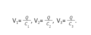
The equivalent capacitance of n capacitors can be computed by considering the voltage of individual capacitors. The potential across the capacitors is

These potentials should be added to give the potential balance.
V = V1 +V2 +V3
Charge Q holds an equivalent capacitance Cs. By entering the potential balance, we get
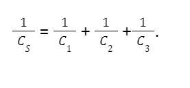
By cancelling Q, we obtain an expression containing the equivalent capacitance connected in series for three capacitors as follows:
Capacitors in parallel
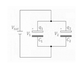
When both capacitor’s terminals are connected to every terminal of a different capacitor, it is said to be connected in parallel. The common voltage (VC) is linked throughout all capacitors connected in parallel. Capacitors in parallel have one constant voltage across the circuit. VC1 = VC2 = VC3 together in a parallel between points A and B.
Q(across AB)=Q1+Q2+Q3
An electric circuit’s components are linked in parallel. The voltage over each resistance will be the same when the resistors are linked asynchronously. Even the polarities will be the same. When a single component collapses, the entire circuit will collapse.
=VC1+VC2+VC3

Formula for the equivalent capacitance Cp of n capacitors connected in parallel
To calculate the parallel network’s equivalent capacitance Cp, remember that the total charge Q held by the network is the summation of all the individual charges:
Q = Q1+Q2+Q3
The relation is used in the left side of the equation Q = Cp V. This holds the entire network. On the right side, we use the relations of three capacitors in the network.
Cp V = C1 V + C2 V +C3 V
This when simplified for three capacitors, we get equivalent capacitance of the parallel network:
Cp = C1 + C2 +C3
Combination of Capacitors in a Diagram
Different capacitors are combined in various configurations to form circuits. A circuit is fundamentally about two factors – voltage and current. When you create a circuit in a “simplified” form, you’re ensuring that the voltage at every end of individual components and the current flowing through those parts stay the same.
At the most fundamental level, there are two large lumps of the circuit to consider. Asynchronous elements are those that have the same current flowing through them. Parallel objects have equal voltage at their corresponding ends. In our example, consider C2, C3, and C4.
If you trace together with your fingertip, you’ll notice that they all share the same current and are, thus, asynchronous. As a result, after simplifying the arrangement, you placed them on a line. Similarly, the most basic way to demonstrate if the items are parallel is to draw them on two parallel lines that are linked at the top and bottom. This is most likely what you did with C5 and C6.
Conclusion
When we connect capacitors in a series, the charge remains constant. The inverse of equivalent capacitance will be the sum of the inverse of capacitors. When we connect the capacitors in parallel, the voltage remains constant. The equivalent capacitance will be the sum of every capacitor. A combination of capacitors can be solved by converting them into the simplest form.
 Profile
 Settings
 Refer your friends
 Sign out


