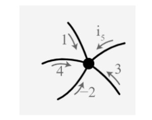
German scientist Gustav Robert Kirchhoff postulated two revolutionary laws for current and voltage in an electric circuit. The two laws were proposed based on the flow of current in the circuit and its voltage variation. The laws are Kirchhoff’s current law and Kirchhoff’s voltage law. These two laws summarised the flow and conservation of the circuit’s current. They are mainly applied to analyse the electric circuits, nodes and meshes. A detailed guide is given below.
History of Gustav Robert Kirchhoff
Gustav Robert Kirchhoff was born in Königsberg, Prussia, on 12 March 1824. The conduction of electricity was his initial focus of study. Kirchhoff developed the laws of closed electric circuits in 1845 because of his study.
Understanding the principles of these rules, which apply to all-electric circuits, is critical to comprehending how an electronic circuit works. Kirchhoff’s laws made him famous in the engineering industry. He also made other discoveries. He was the first to prove that an electrical impulse could travel faster than light. Aside from this, Kirchhoff made contributions in the field of blackbody radiation and spectroscopy.
Terminology for circuital analysis
A few common terms used in the circuital analysis are discussed below.
Circuit: A circuit is a closed path where current flows.
Path: A path is a single line made up of circuit parts and sources.
Node: A node is a terminal or a junction at which two or more elements are connected, forming a common point for multiple branches.
Branch: A branch comprises elements such as resistors and sources that connect two nodes.
Loop: A loop is a closed path with only one count of each element.
Mesh: A mesh is an open-loop, open path that contains no elements.
Kirchhoff’s law and simple applications
Circuit analysis
Kirchhoff proposed a set of rules in 1845 that address the current and conservation of energy in electrical circuits. Kirchhoff’s voltage and current laws are the records for these two laws. These principles aid in determining the resistance value of a complex network, or impedance in the case of AC, as well as the flow of current in the network’s numerous streams.
Wheatstone’s metre bridge
Another simple application of Kirchhoff’s law is its use in Wheatstone’s metre bridge. The Wheatstone bridge is a circuit with a special arrangement. The arrangement comprises four resistors and a galvanometer in the middle of two among them. This bridge is mainly used for the analysis of mesh and nodes. The metre bridge is also an instrument that works on the Wheatstone bridge’s principle.
Kirchhoff’s current law (first law)
Charged particles pass around the circuit, generating current. The rate at which this charge travels through any point in the circuit is known as current. The conservation of charge is a fundamental principle in physics. In the aspect of circuits, it means that, as current is the rate of flow of charge, the current streaming through a node must be identical.
Representing the current law in the mathematical format:
According to Kirchhoff’s current law, the currents in the three wires at the node according to figure must be represented in the form of:
IAO + IBO = IOC
I1 + I2 = I3
It is crucial to understand what the current signs in the diagram mean: a positive current indicates that the currents are travelling in the directions indicated in the figure. Positive charges would flow from the plus of the battery around the circuit to the minus in the direction of directions.
Now simplifying further, the mathematical expression is:
I1 + I2 = I3
I1 + I2 – I3 =0
This states that current flow through the node, keeping the sign convention in consideration the sum of all currents flowing through the circuit is zero or conserved.
It is the generalised form of Kirchhoff’s current law.
Note: Kirchhoff’s current law is typically represented by all currents flowing either towards or away from the node.
Kirchhoff’s voltage law (second law)
Depending on the device, charge carriers getting passed through a circuit acquire or dissipate electrical energy as they pass through it (cell or resistor, for example). This is owing to the fact that the forces acting within the elements cause work to be done on or by them. By the time it has gone around the circuit once, the total work done on a charge carrier by electric forces in supply elements (such as cells) must match the total work done by the charge carrier in other units (such as resistors and lamps).
Suppose there are four resistors joined in a circuit, as shown in the figure:
Then the mathematical format of the law is:
V1 + V2 + V3 + V4 =0
Kirchhoff’s voltage law is applicable toward any loop with any number of components. When a circuit has junctions, one must be cautious about choosing only one loop each time one accesses this law. In essence, this means that at each junction, one must only take one alternative.
The generalised format of writing is:
Conclusion
Gustav Kirchhoff’s laws improve one’s grasp of how to solve and apply electrical circuits. Kirchhoff’s first law describes the relationship current flowing into a node, or junction equals the total current or charge flowing out of the node. It is based on the charge conservation principle. The junction rule is another name for this. The sum of voltage drops equals the sum of voltage rises, according to Kirchhoff’s second law. This law is based on the concept of energy conservation. The loop rule is another name for this.
 Profile
 Settings
 Refer your friends
 Sign out


