Direct Current (DC) does not change its direction from time to time. However, the direct current sources are considered to be the DC sources. This type of charging current found in a circuit is known as the Alternating Current or AC. Thus, AC is the current that alters and signifies how the electrons move from one direction in the opposite way of a conductor. Normally, it flows from the negative to the positive direction, unlike other electronics at home.
Resistors, Inductors, and Capacitors
Many electrical circuits feature resistors, inductors, and capacitors connected across an AC source or a combination of any two or all three of these components connected across an AC source. When a resistor is used, the current flowing through it is in phase with the voltage source. In the case of a capacitor or an inductor, however, either the current lags or it leads the voltage source by some amount. This is where the concept of phasors comes into play to connect the current and voltage.
The sinusoidally fluctuating values V and I are represented by the vertical components of phasors I and V. The amplitudes or peak values Im and Vm of these oscillating quantities are represented by the magnitudes of phasors I and V. The projection of voltage and current phasors on the vertical axis are the current and voltage values at that moment, respectively.
What is an inductor?
An inductor is a passive component that is majorly used in power electronic circuits for storing magnetic energy. In an electric current, the inductor plays the most important part, where most power electronic circuits store the excess amount of energy in a magnetic energy form. The inductor is also further defined as the reactor, choke, or coil. The inductor consumes the excessive charge or loses power when it is urgently needed and serves all other electrical uses. These are further used for balancing the current flowing within it.
Furthermore, the inductor can also help measure the amount of voltage obtained for a particular rate of change in the current.
Relationship between voltage and current in the AC circuit
When the AC voltage is applied to an inductor, the relationship between voltage and current in the AC circuit is as follows:
V= L×di/dt
di/dt= V/L
di/dt= Vmsinωt/L…. (1)
After integrating equation (1)
i = ∫ Vmsinωt/ Ld×t
i = – Vmcos ωt/wL
i = Vmsin (ωt- 90)/ ωL
i = imsin (ωt- 90)
Where, Vm = Maximum voltage, ω = Angular frequency, Im– Maximum value of current.
The expression for inductive reactance:
V= Vmsinωt
i= imsin( ωt – 90)
i = -imcosωt
im = Vm/ ωL
im = Vm/XL
Where, XL = Inductive reactance, Inductive reactance XL = ωL, and Inductive XL = 2πfL.
The SI unit of inductive reactance is denoted by Ohm. It is equivalent to the frequency of the angular, which means it increases when the reactance is increased and decreases when the reactance is decreased. Moreover, if the value of the DC is 0, XL will also become 0.
AC Voltage
An AC power source’s output is sinusoidal and fluctuates with time according to the equation: v(t)=V0sin(ωt). The instantaneous voltage is v(t). V0 is the source’s maximum output voltage, often known as the voltage amplitude (book Vmax), which is the AC voltage’s angular frequency.
Rules for Drawing a Phasor Diagram
Rule 1: The phasor’s length is proportional to the amplitude of the wave being portrayed.
Rule 2: In circuits with L, C, and R in series, the phasor indicating current is usually shown horizontally and referred to as the reference phasor. This is because all components in a series circuit share the same current.
Rule 3: The phasor representing the supply voltage is drawn always in the reference direction in parallel circuits with L, C, and R connected in parallel. This is because all components in a parallel circuit share the same supply voltage.
Rule 4: All phasors are regarded to rotate in an anticlockwise orientation.
Rule 5: For each phasor in a diagram, the same sort of value (RMS, peak, etc.) is utilised – not a mix of values.
Conclusion
Direct Current (DC) does not change its direction from time to time. However, the direct current sources are considered to be DC sources. Many electrical circuits feature resistors, inductors, and capacitors connected across an AC source or a combination of any two or all three of these components connected across an AC source. In an electric current, the inductor plays the most important part, where most power electronic circuits store the excess amount of energy in a magnetic energy form.
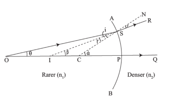
At point O, a point object is placed on the principal axis of the concave surface.
The ray OS, incident at the point S of the concave surface, travels along SR after refraction. As n2>n1, the refracted ray bends towards the normal CSN. Another ray OP, incident normally on the concave surface, is undeviated. The two refracted rays do not intersect in reality but appear to meet at point I in Medium 1.
Thus, I is the virtual image of the object placed at O.
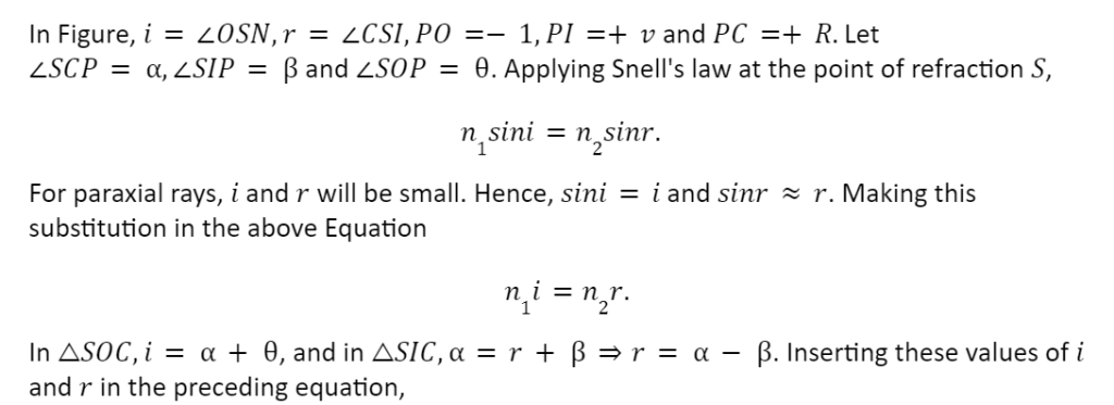
In Figure,i=∠OSC,r=∠NSR=∠ISC,
PO= object distance =-u,
PI= image distance =-v
and radius of curvature =PC=-R.
Let SCP=,∠SIP= and SOP=. Snell’s law is applied at the point of refraction S,
n1sini=n2sinr.
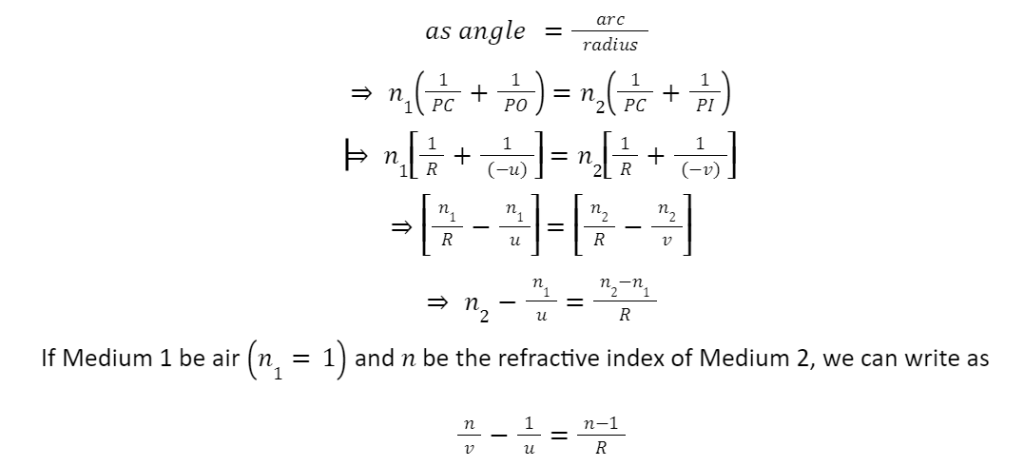
For paraxial rays or small aperture, i and r will be small. Hence, sinii and sinrr. Making this assumption, we can write as
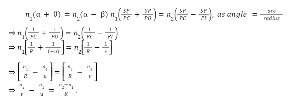
n1i=n2r.

If Medium 1 be air n1=1 and Medium 2 has a refractive index n2=n, then we can write the above Equation as
n/v – 1/u = n-1 / R.
When an object is placed in the denser medium, the image of the object is formed by a concave surface dividing the two mediums. This is shown in the Figure below.

Refraction at a convex surface:
When light refracts on a convex surface, it creates a real or virtual image. We will discuss the two cases separately.
When the image is virtual: Consider a convex surface AB separating two media of refractive indices. When n2n2>n1, as shown in Figure.
P is pole, and C is the centre of curvature of the convex surface.
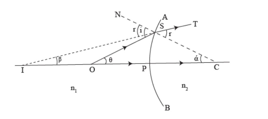
At the point 0, point objects are placed on the principal axis of the curved surface. The ray OS, incident at the point S on the convex surface, travels along ST after refraction.
As n2>n1, the refracted ray bends towards the Normal CSN.
Another ray OP incident, normally on the convex surface, is undeviated.
The two refracted rays do not intersect in reality but appear to meet at point I.
Thus, I is the image of the object placed at O.
OSN=i,∠CST= NSI =r
PO=-u,PI=-v ,PC=+R.
Let SCP=,∠SIP= and SOP=.
Applying Snell’s law at the point of refraction, n1sini=n2sinr.
For paraxial rays, i and r will be small. Hence, sini=i and sinr=r. Making this substitution in Equation n1sini=n2sinr.

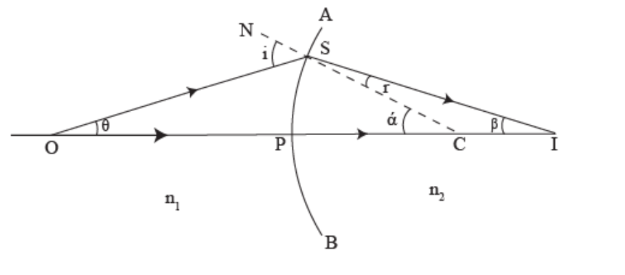
When the image is real: Consider a convex surface AB separating two media of refractive indices n1 and n2 (n2>n1), as shown in Figure.
Let P be the pole and C be the centre of curvature of the convex surface. Let a point object be placed at point O on the principal axis of the convex surface. The ray OS, incident at S, goes along SI after refraction at S. As n2>n1, the refracted ray bends towards the normal CSN. Another ray OP, undeviated. The two refracted rays intersect at I in Medium 2 . Thus, I is the real image of the object placed at O.

Lateral magnification:
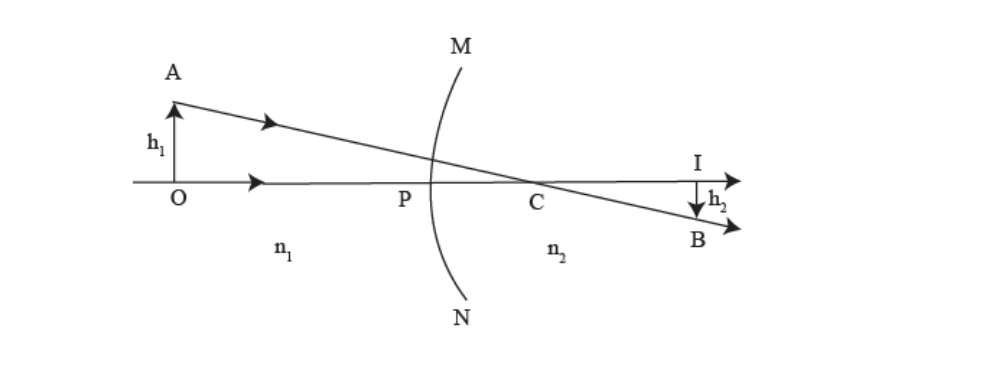
Consider an extended object AO placed in Medium 1 (refractive index n1 ) facing a convex spherical surface MPN of Medium 2 (refractive index n2 ). Rays originating from A and O directed towards centre C will travel undeviated into Medium 2. Let the image formed be BI, as shown in Figure.
Its position may be located by using Equation
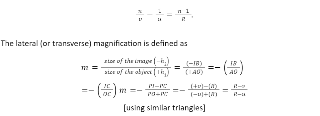
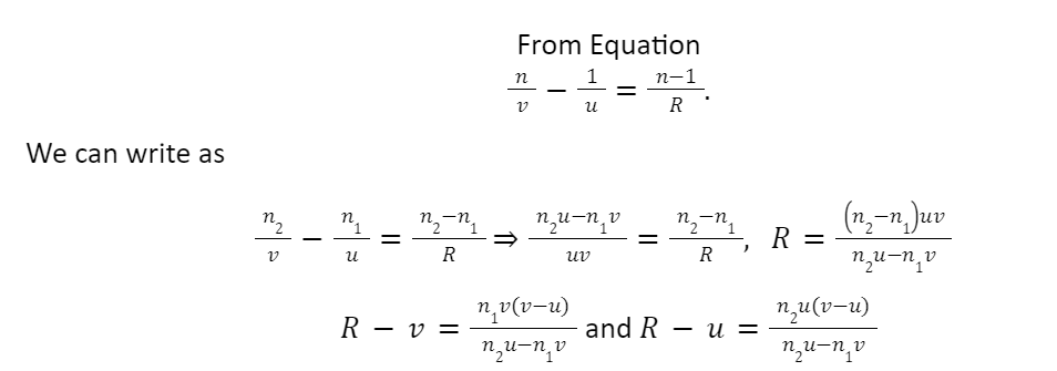
Thus,
Hence,

Conclusion
With this, we come to the end of the topic of Refraction at Spherical Surfaces and by Lens. Refraction is the bending of light (it also happens with sound, water and other waves) because it passes from one item into another. We hope the topic is clear to everyone.
 Profile
 Settings
 Refer your friends
 Sign out


