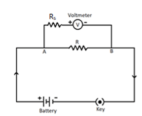
A voltmeter is an electrical instrument that helps measure the potential differences across any device connected to a circuit. A voltmeter is connected in parallel to a device to measure the device’s voltage.
Ideally, a voltmeter poses high resistance. Thus, it is not connected in series since if it were, it would pose high resistance to the current, and therefore no current would flow. Hence, it is wired in parallel with the device connected. This instrument has similar connection polarity, which means the positive terminal of the voltmeter is connected to the supply’s positive polarity and vice versa.
1888 – Edward Weston developed the first voltmeter.
1880 onwards – William Stanley developed the magnetic coil-driven voltmeter.
1897 – Oliver B. Shallenberger found a way to create a voltmeter from the galvanometer.
1922 – E.B. Moullin created the vacuum tube voltmeter.
1954 – Andrew Kay invented the first digital voltmeter.
The voltmeter follows the principle of Ohm’s Law. The voltmeter is wired parallel to the devices connected in an electric circuit. It is not connected in series since if it were, it would pose high resistance to the current, and therefore no current would flow. The voltmeter has a similar connection polarity, which means the positive terminal of the voltmeter is connected to the supply’s positive polarity and vice versa.
DC voltmeters are marked with polarity. Accordingly, the positive terminal of the voltmeter is connected to the supply’s positive polarity and vice versa. The AC voltmeter can be powered up anyways since it has no polarity indications.
The sensitivity of a voltmeter is the inverse of the current (Ifsd) required for the full-scale deflection of the voltmeter needle. Its unit is Ω/V.
Voltmeter Sensitivity, S = 1 / Ifsd Ω/V
As per Ohm’s law, I = V/R.
Therefore, Ifsd can be written as the ratio of the voltage range V of the voltmeter to the total resistance of the circuit Rt.
S=Rt / V
=Rm + Rs / V [Rt = Rm + Rs]
Where
Digital voltmeters are essentially analog to digital converters (integrating converters), which are used to convert analog signals into a train pulse. As the input signal increases, so does the number of train pulses. A calibration procedure (counter) counts the number of pulses and the duration of the train of pulses and displays the voltage on the decimal display.
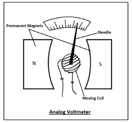
In an analog voltmeter, there is a coil called a moving coil suspended between two permanent magnets. Current is passed through this coil. Voltage is applied. Due to the applied voltage, a magnetic field is generated in the coil, whose direction is opposite to the permanent magnets. The pointer or needle is pivoted on the moving coil. The magnetic field applies a torque on the needle, causing it to deflect. The deflection of the needle is directly proportional to the applied voltage.
The vacuum tube voltmeter (VTM) is used to measure AC and DC voltages using the vacuum tube as the amplifier. As a result of using the vacuum tube, the voltmeter is highly sensitive, so even feeble signals can be detected. The signal to be measured is directly fed to the vacuum tube. Through the vacuum tube, the signal is amplified and sent to the deflecting meter. As compared to the other meters, the VTM draws minimal current.
The conversion of a galvanometer to a voltmeter can be done by connecting a very high resistance series to the galvanometer. The potential difference in such a case will be the sum of the potential difference across the galvanometer and high resistance. The range of the voltmeter will be determined by the value of high resistance connected in series. The voltmeter range is given by
V = Ig (R + G)
Or, Ig R = V – Ig G
or, R = (V/Ig) – G
Where,
Ig = The full-scale deflection current in the galvanometer
R = Resistance of the voltmeter
G = Resistance of the Galvanometer.
The effective resistance of the voltmeter is given by G + R. This effective resistance is very high. So, the voltmeter is connected in parallel to draw the least current.
Ammeters are electrical devices that determine the amount of electricity (in amps) passing through an electrical circuit.
In contrast to Voltmeter, the Ammeter must be linked in series with the two points while determining the current flow between two points. An ammeter’s internal electrical resistance should be very low. A zero-resistance ammeter is an ideal ammeter.
The Uses of Voltmeter –
In this article, we learned about voltmeters. Voltmeters determine the potential difference between two locations in an electrical or electronic circuit. We learned the working principle of analog voltmeter, digital voltmeter and vacuum tube voltmeter. We got to know how to convert a galvanometer into a Voltmeter.



 Profile
 Settings
 Refer your friends
 Sign out