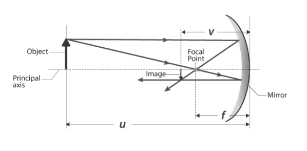
There are a few significant terms to be understood before mentioning the mathematical landscape of Ray Optics. The object position, represented by u, is the coordinate of the object with respect to the origin. As a convention, the origin in geometrical optics is taken as the Pole of the lens or the curved mirror involved. Similarly, the image position with respect to the origin is represented by the symbol, v. The heights of the object and the image are represented by the symbols ho and hi, respectively. Images that appear upright about the object are amalgamated in positive notes, whereas the inverted images are amalgamated with negative notes. Let us understand some basics of Ray optics before Magnification.
The Laws of Reflection.
The normal of a curved surface always passes through the centre of the curve. All distances are calculated from the mirror’s pole. The light incidence direction is usually taken as positive in sign convention. The distance measurement between two points in the opposite direction of incident light is taken as negative. However, the choice of the positive direction is arbitrary.
LIGHT REFRACTION
The Laws of Refraction:
sin i
= constant
sin r
There is also a wave nature of light that is at play. According to wave nature, light experiences phenomena such as interference and diffraction. In general, light is electromagnetic energy that generates the sensation of vision. Let us explore how the wave nature light is idealised as the ray optics in specific situations.
– The wavelength of visible light ranges from 400 to 750 nanometers.
– Light travels at the quickest speed conceivable in nature in a vacuum, which is 3.0 x 10⁸ m/s
– Because light waves have such a small wavelength in comparison to the size of regular things, they are thought to move in a straight path between two sites.
– A beam of light, on the other hand, is an idealisation of the wavefront. It’s a light route that runs in a straight line between two places. A light beam is made up of a collection of rays.
– Reflection, refraction, interference, and diffraction are examples of optical phenomena.
We can accurately describe the location and size of an image by using the rules of ray tracing and making a scale drawing with paper and pencil. However, the real advantage of ray tracing is that it allows you to see how images are formed in a variety of situations. We use a pair of equations derived from a geometric analysis of ray tracing for thin mirrors to obtain numerical data. The mirror formula is as follows:
Mirror equation
Ray tracing should be done by following the following steps:
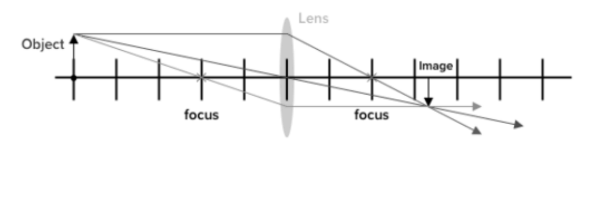
Consider the case of an item that is far away from the convex lens, as shown in figure 2. We follow the trajectories of chosen incoming light originating from one place on the surface (in this example, the top of the person’s head) to establish the position and size of the picture generated. Rays can move in many directions from this point, but we’ll focus on a few that have well-defined paths:
2nd diagram
The magnification m is defined as the ratio of image height to object height ho and hi. The following relationship exists between magnification and the positions of the image and object:
m = hi/ho = -v/u
And the similar formula for a lens is given by:
m = hi /ho= v/u
These equations can be used to find out the magnification of the object without having data about its height.
Lenses may be found in a wide range of optical equipment, from a simple magnifier to a camera lens to the lens of a human eye. The term “lens” is derived from the Latin word “lentil,” which has a convex lens-like form. All light rays entering the convex lens with comparison to its axis intersect at a certain point on the opposite side. The principal axis is a line that passes through the lens’s centre and is perpendicular to it. The light rays coming parallel to the principal axis will either converge or diverge on a point on the principal axis called the focus. A collection of rays passing through the lens shows how the beam changes direction as it enters and exits the lens.


 Profile
 Settings
 Refer your friends
 Sign out