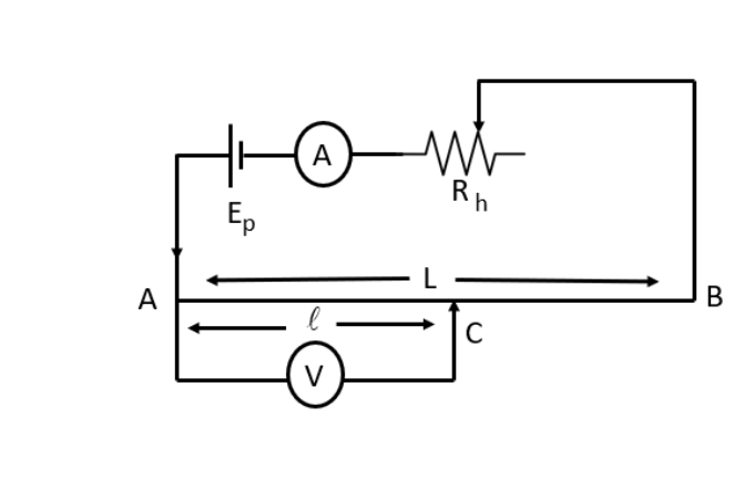
Potentiometer, an integral component of current electricity. It is a device that allows you to evaluate the electromotive force between two cells to gauge the difference in potential between two points on an underlying circuit. It is also used to determine the internal resistance of cells. Potentiometers are employed in large quantities in electronic equipment and can adjust electronic circuits based on the achieved results.
In these study material notes on the Potentiometer – principle and its applications, we will see that the potentiometer is an adjustable resistor with three terminals in which two of the terminals are fixed while the other one is variable. The advantage of a potentiometer is that it does not draw electric current directly from the source of voltage. Instead, the resistance is structured manually to regulate the flow of electricity.
Now, let us look more in detail with study material notes on the Potentiometer – principle and its applications.
The potentiometer is made up of a long resistive wire (L) and an electric motor cell battery current (EMF V).
Suppose a primary circuit configuration connects two ends of L to battery terminals. The principal circuit has been connected to Galvanometer G as well as the opposite is connected to the cell with whose EMF E is not yet assessed.
The basic principle is based on the wire’s potential segment that is directly proportional to its length with continuous current flow and a homogeneous cross-sectional area.
V = IR
Where,
V is Voltage
I is Current
R is Total resistance
Similarly,
R = ρL/A and V = I × (ρL/A)
where,
R is Total Resistance
ρ is Resistivity
A is Cross-sectional Zone
Now, I is also constant for a rheostat as ρ, and A are constant.
Lρ/A = K
V = KL
E = Lρx/A = Kx
where,
x: length of Potentiometer wire, E: cell with Lower EMF, and K: constant
Since the potential difference is equal to zero, there is no current flow. So, it suggests that the galvanometer G is not detecting anything.
The length of the x is called the zero point. When you have both x and K, you can determine the unidentified electromotive force (EMF).
E = Lρx/A = Kx
Since EMF is composed of two cells, let L1 be the null length of the cell that was the initial cell with EMF E1 while L2 is the length that counts as the Null Point of the second cell that has EMF E2.
E1E2 = L1L2
Rotary and Linear potentiometers are considered among the most common types of potentiometers. This can be further classified as per the wiper movement.
When the wiper is in a circular direction, it is referred to as the Rotary Potentiometer. Both a linear and rotary potentiometer work the same way. The primary difference is that the rotary potentiometer converts the rotary motion into different resistance.
Rotary Potentiometers are classified into these categories:
Linear Potentiometer works the same way as the rotary potentiometer. However, rather than the circular resistance, there is linear resistance. Linear Potentiometer can be further classified into these categories:
Apart from a rotary and linear potentiometer, membrane potentiometer and digital potentiometer are the two other potentiometers available.
Potentiometers function like a voltage divider, which is why they are employed in a variety and wide spectrum of applications. A few of them are as follows:
The basic principle of the potentiometer’s functioning can be described as – the voltage on the wire directly proportional to the distance. It can be described as V = IR. The potentiometer works based on the voltage across the wire and its length, which has a uniform cross-sectional area with constant flow. This is an inverse proportionality relationship.



 Profile
 Settings
 Refer your friends
 Sign out